Duet damaged => 12v -> 3.3v not working
-
I'd like to ask for a help in fixing my Duet board.
So I succesfully connected everything and managed to do few prints. And now after connecting hobby servo to pins shown in picture I managed to damage it somehow. After connecting power servo rotated a bit.
When I plug 12 V, VIn led is ON but 3.3V is not. When I plug USB duet is fine and i can connect via WIFI.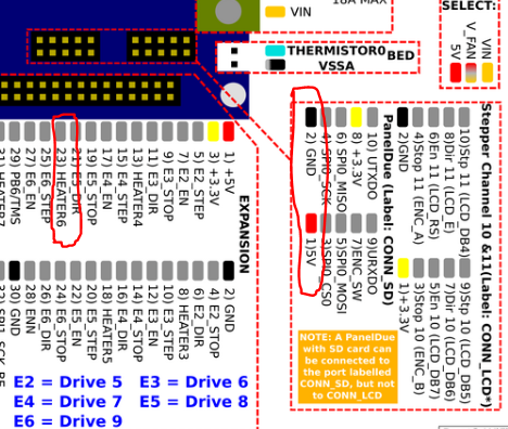
-
Does the small square chip labelled U3 look damaged?
What size was the servo? Large servos put a substantial amount of energy back into the 5V rail when they brake.
-
It doesn't look damaged at all.
Well I guess it is large.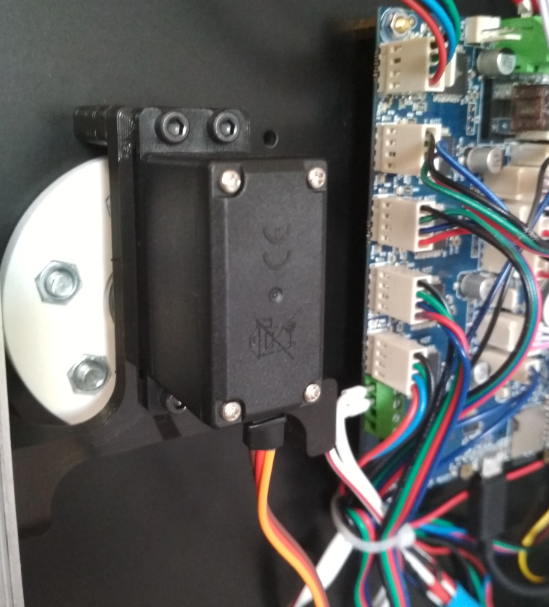
-
I have V1.04b revision of Duet.
-
You can find the schematic diagram here if it helps https://github.com/T3P3/Duet/blob/master/Duet2/Duet2v1.04/DuetWifi_Schematic_v1.04.pdf
In page 3, U3 and the circuitry around it reduces vin to 5V, and U2 reduces the 5V to 3.3V.
If the 5V doesn't exist and you connect a USB, 5V is fed from the USB connector via diode D13. If the 5V LED is on only when you connect USB, then the problem may be with the 5V supply, rather than the 3.3V.
-
Thank you for suggestions.
I just did some probing. And there is 12 V on R92 and 0V on D2, so I guess that U3 has been damaged and I will have to replace it. -
@steca said in Duet damaged => 12v -> 3.3v not working:
I guess that U3 has been damaged and I will have to replace it.
That's an inexpensive IC. I presume that it dissipates heat via the large tab at the bottom so you need to make sure that hidden tab is soldered well to the PCB (?). Maybe with solder paste and hot air station.
-
I'm a bit concerned about if I will manage to unsolder/solder it with hot air without messing all this resistors/capacitors around.
I'm wondering if it will be wise to do it on my own.
My question is if such replacement could be done by supplier under warranty? -
you typically shield the surrounding components with kapton or aluminium tape, use more time preheating the board and less time at liquid temp. it is an expensive board to practice on, you may be better off taking the chip and the board to a phone repair center (that does actual repairs) and see if they'll do it for a reasonable fee.
and yes, bottom pad is usually for thermal
-
Meanwhile you may be able to run it with external 5V as the schematic suggests. Just make sure it can provide sufficient current.
-
That is a very large servo. My tests with a smaller one showed the 5V supply going up to 8V at the end of servo movement. With your large servo it will be much worse. I suggest you use a separate 5V supply for the servo, or else connect a 6V power Zener diode in parallel with it to to clamp the voltage.
Edit: also, the motor current drawn by that servo may exceed the rated current of the regulator. In theory it's short circuit protected, but its best not to rely on that.