Problem with gantry leveling (4 z-motors on voron2)
-
I'm trying for several weeks to bring the gatry leveling on voron2 to work. Here the result of two runs of leveling, as you can see, the result has become worse as before:
Leadscrew adjustments made: 9.244 -13.301 -0.916 0.690, points used 4, deviation before 3.836 after 0.000
Leadscrew adjustments made: 7.526 -3.585 1.419 2.157, points used 4, deviation before 3.058 after 0.000
Here are relevant parts from my configuration
M667 S1                 ; corexy mode
M208 X-5:355 Y-4:354 Z0:500 S0
M574 X2 Y2 Z0 S0        ; endstops

M584 X0 Y1 Z5:6:7:8 E3               ; motor bindings
M671 X405:405:-55:-55 Y355:-80:-80:355 S20       ; Z drive positions

M569 P0 S0      ; X motor direction
M569 P1 S0      ; Y motor direction
M569 P5 S1      ; Z1 motor direction
M569 P6 S0      ; Z4 motor direction
M569 P7 S1      ; Z2 motor direction
M569 P8 S0      ; Z3 motor direction
and leveling commands
G30 P0 X50  Y50  Z-10000 H+0.00
G30 P1 X50  Y300 Z-10000 H+0.00
G30 P2 X300 Y300 Z-10000 H+0.00
G30 P3 X300 Y50  Z-10000 H+0.00 S
Does anyone have hints about what I'm doing wrong or what else I could try?
Thanks -
are your stepper motors in the correct order?
https://duet3d.dozuki.com/Wiki/Bed_levelling_using_multiple_independent_Z_motors
The M671 command must come after the M584 command and must specify the same number of X and Y coordinates as the number of motors assigned to the Z axis in the M584 command; and these coordinates must be in the same order as the driver numbers of the associated motors in the M584 command. -
I've tried severel values for the z motor mapping and forgot set back the right values. The correct order looks like this:
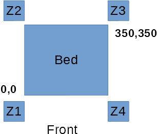
M671 X-55:-55:405:405 Y-5:430:430:-5 S20 ; Z drive positionsThe M671 command come direct afte M584 command. The picture below shows the real mapping of the z motors.
The z motors connected to the DueX board as follow:
Z1 = DueX E2 Motor (Drive 5)
Z2 = DueX E3 Motor (Drive 6)
Z3 = DueX E4 Motor (Drive 7)
Z4 = DueX E5 Motor (Drive 8 )I hope thes helps. Thanks
-
Hi,
I recently converted my DBOT to 3 Z stepper to try out auto-leveling.
While I am very happy with the mechanical arrangement I'm not so impressed with the auto-leveling. So far it is not doing as well as I used to do manually.
Still hoping to discover if something is wrong.
Frederick
Printers: A FT-5 with the 713 upgrade bits, a custom MarkForged style, a small Utilmaker style, a small CoreXY from kit and a E3D MS/TC setup. Various hotends. Using Duets (2 and 3) running 3.4.6
-
can you post the mesh bed grid before the leveling and after?
-
@fcwilt
How many iterations of the leveling do you do? I found I had to run it 2-3 times (I have a macro that does it) with mine to get it bang on. I am running a piezo probe and it is only out by 0.003mm after running it 3 times. When I run mesh leveling after it seems to coincide with what I get with the leveling. I am also doing it with 4 motors however. Measuring the distances must be done really accurately as well. I spent quite a bit of time doing it.Regards
SamCustom Core-XY
-
@npukol, that config looks correct to me, provided that you really do have the Z1 motor connected to driver 5 and so on, and +X is towards the right in your diagram.
Which firmware version are you using?
Using 4 leadscrews to level the bed or gantry only works if the mechanics has sufficient flexibility to twist in response to differential adjustment of the leadscrews (which is why rigid mechanics and 3 leadscrews is normally preferred). The first adjustment shown in your original post is very large, 7mm to the front left motor and -3mm to the rear left one. This indicates that the leadscrews need to impart a significant twist to the gantry in order to level it. Are you certain that the motors can make that correction without the leadscrews binding?
Duet WiFi hardware designer and firmware engineer
Please do not ask me for Duet support via PM or email, use the forum
http://www.escher3d.com, https://miscsolutions.wordpress.com -
@samlogan87 said in Problem with gantry leveling (4 z-motors on voron2):
@fcwilt
How many iterations of the leveling do you do?I've repeated it several times. Each time the "after" numbers are zero but the "before" number doesn't vary that much.
Measuring the distances must be done really accurately as well. I spent quite a bit of time doing it.
What distances do you mean?
-
what are the before numbers? Large? The measurements I was talking about was the leadscrew positions.
Regards,
Sam -
@dc42 said in Problem with gantry leveling (4 z-motors on voron2):
@npukol, that config looks correct to me, provided that you really do have the Z1 motor connected to driver 5 and so on, and +X is towards the right in your diagram.
Which firmware version are you using?
I'm using the latest version: 2.04RC1. But I also tried it with versions 2.03 and 2.02.
Using 4 leadscrews to level the bed or gantry only works if the mechanics has sufficient flexibility to twist in response to differential adjustment of the leadscrews (which is why rigid mechanics and 3 leadscrews is normally preferred). The first adjustment shown in your original post is very large, 7mm to the front left motor and -3mm to the rear left one. This indicates that the leadscrews need to impart a significant twist to the gantry in order to level it. Are you certain that the motors can make that correction without the leadscrews binding?
Manually aligning the gantry works and the gantry is also flexible enough. The problem is that without power, the rear motors (Z2, Z3) go down a bit because of the weight of the XY motors on the gantry.
The leveling itself works, only the adjusment is wrong. In my opinion, this may be due to the wrong mapping of Z motors or the direction of the adjusment itself. I have no idea how to fix this (I will check the connections of the Z motors tonight, i realy hope i find the error there).
Thanks
-
please post the mesh grid picture before and after. in that you can see how it is being adjusted.
-
@samlogan87 said in Problem with gantry leveling (4 z-motors on voron2):
@fcwilt
How many iterations of the leveling do you do? I found I had to run it 2-3 times (I have a macro that does it) with mine to get it bang on. I am running a piezo probe and it is only out by 0.003mm after running it 3 times. When I run mesh leveling after it seems to coincide with what I get with the leveling. I am also doing it with 4 motors however. Measuring the distances must be done really accurately as well. I spent quite a bit of time doing it.I can only do one iteration without any problems, at the second try I have to worry about my printed parts from the gantry.
-
I would agree it looks like in this case the stepper connection order doesn't match the defined order, and would be the first thing I check.
A good method for troubleshooting leveling issues once you're 100% sure the steppers are correct is to create a 4 point mesh that corresponds to your 4 point probe, so you're hitting the exact same points with each. The mesh gives you nice visual data for a clue as to what's going on. Then you can iterate G32 / G29 to resolve. If your fixed rails (Y rails on a voron, I believe) are not parallel, then you can never get your leveling results lower than the skew of the rails. A 4 point mesh output can help show that issue. (you can also then reduce the spacing value by half to get a 9 point mesh, which can add even more insight).
To get the points equal I create the largest mesh I can for G29, probe it, then hover my mouse over each point. Use those X,Y coordinates to create your bed.g for G32.
Hope this helps.
Co-Creator of the RailcoreII CoreXY printer
https://www.thingiverse.com/thing:2407174 -
You say that the bed is quite flexible, how are you achieving the flex ?
I had an binding issue on my triple lead screw printer using LM8UU bearings that i left a little loose on the mounting to the bed but it wasn't enough flex, i ended up adding spherical bearings which i specced to accept Igus bushes.
After i did that my minute amount of binding i had went away and the "leveling" (an incorrect term i hate) issues i had using one of David's IR sensors all went away too.

-
@CaLviNx said in Problem with gantry leveling (4 z-motors on voron2):
You say that the bed is quite flexible, how are you achieving the flex ?
I had an binding issue on my triple lead screw printer using LM8UU bearings that i left a little loose on the mounting to the bed but it wasn't enough flex, i ended up adding spherical bearings which i specced to accept Igus bushes.
After i did that my minute amount of binding i had went away and the "leveling" (an incorrect term i hate) issues i had using one of David's IR sensors all went away too.
The Voron2 has a fixed bed and raises and lowers the XY gantry with 4 belted motors. The gantry is designed to accommodate this.
-
Unfortunaly the wiring of the Z motors are correct.
@kraegar I played around with the mesh and noticed the following behavior: if i put the gantry at one point down (rotate for example Z4 motor) the Z value on this point increase. Is the behavior correct, should not the Z value decrease?
Edit: Sorry, the behavior is correct, it was my mistake. -
@Veti said in Problem with gantry leveling (4 z-motors on voron2):
please post the mesh grid picture before and after. in that you can see how it is being adjusted.
this would really help to visualize the problem
-
Thanks for the link, nice base for a printer, But I disagree that movement is designed in though, if it is as it looks in the video to be x4 linear rails attached to the gantry, that by its very nature is enough to constrain the gantry (unless you use very cheap linear rails with lots of slop in them of course), what should happen for it to be free to move is x4 spherical pivoting links between the gantry where they attach to the linear rail.
It doesn't take much binding to throw the whole thing off.
Edit: I have looked at the Voron Docs, and my god Heath Robinson or what, immensely over complicated is an understatement.
But I will have to admit that it does look like a certain amount of articulation has been designed into the gantry, but its execution with two printed plastic surfaces in friction contact with each other is a recipe for disaster though.