Pressure advance doesn't affect the printed model
-
@skayred said in Pressure advance doesn't affect the printed model:
could it be the problem, that I have the wrong version that just doesn't support PA?
No, it should be supported regardless.
Setting pressure advance in config.g and then sending a new command later is fine. The most recent command will take over. When changing PA on the fly there may be a brief pause at the next segment. You can send M572 D0 in the console to get a read back of the currently set value if you want to verify that it's set.
M350 X64 Y64 Z64 E64 I1
Interpolation to x256 microstepping only works when using x16 microsteps on the Duet Wifi. You'll likely notice quieter operation if you switch back to x16 with interpolation. The other benefit is lower overhead on the CPU which could lead to missed steps on high speed moves. You can check if this is effecting you by sending M122 in the console and looking for the hiccup count.
I suggest pushing further with your speed testing and increasing the PA value.
-
So, I made a g-code with PA from 0 to 1, and it finally shows some difference. But my PA should be set to:
M572 D0:1 S0.64So, do I have to worry about such a high value or it is normal?
-
@skayred said in Pressure advance doesn't affect the printed model:
So, do I have to worry about such a high value or it is normal?
Based on your testing it's normal for you. Only way to be sure it to do some more testing of actual models and watch for anomalies.
-
@Phaedrux will try to print the propeller because why not

-
Thank you, guys!
The propeller was printed perfectly, with no stringing and blobs so I can fit it to the shaft, finally! -
@skayred said in Pressure advance doesn't affect the printed model:
Thank you, guys!
The propeller was printed perfectly, with no stringing and blobs so I can fit it to the shaft, finally!Great! Photo?
-
@dc42 Can you edit the documentation to say that values of higher than 0.2 is very normal and maybe necessary for bowden setups? I even have some PC filaments that needed 0.68 for a 100mm direct drive setup.
What I have found is that the PA necessary is linearly related to the length of filament between the drive gears and the heat break. I needed pretty much exactly 1/5th the PA when i switched from a 100mm bowden to a 20mm direct drive.
This will reduce confusion with future users. -
@dc42 hello,
now it looks like this:
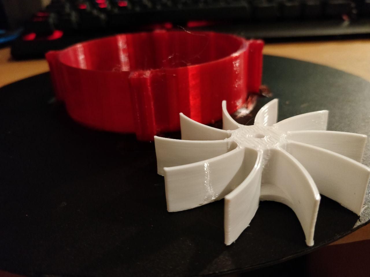
This is the propeller side with most retractions between wings. Not really invisible but good enough for me. I think I will need to experiment with retractions but the generally proper value of PA makes everything better.
But, as was said there, documentation is really confusing, I was not even trying to make PA much higher than recommended. -
@NitroFreak said in Pressure advance doesn't affect the printed model:
@dc42 Can you edit the documentation to say that values of higher than 0.2 is very normal and maybe necessary for bowden setups? I even have some PC filaments that needed 0.68 for a 100mm direct drive setup.
What I have found is that the PA necessary is linearly related to the length of filament between the drive gears and the heat break. I needed pretty much exactly 1/5th the PA when i switched from a 100mm bowden to a 20mm direct drive.
This will reduce confusion with future users.Yes I can update the documentation.
-
@NitroFreak I've made some changes to flesh out the documentation a bit. https://duet3d.dozuki.com/Wiki/Pressure_advance any feedback welcome.
-
The PA test procedure with the large cylinder is very interesting. I will give it a try. Possibly it can even be automated with slicer gcode conditions similar the to ones used for heat towers.
{if layer_z==1.6} ; T tower floor 1 M104 S225 {elsif layer_z==11.6} ; T tower floor 2 M104 S220 ... {endif} -
@zapta said in Pressure advance doesn't affect the printed model:
Possibly it can even be automated with slicer gcode conditions similar the to ones used for heat towers.
Yes exactly.
-
@Phaedrux said in Pressure advance doesn't affect the printed model:
Yes exactly.
I run this PA calibration and it was easy to set up and interpret the results. Best value is 0.15 for my BMG/Titan direct extruder. I expected it to be lower.
I use script in the Prusa Slicer's Before Layer gcode section (this one is after I narrowed down the search range)
{if layer_num== 1}M572 D0 S0.125
{elsif layer_num== 25}M572 D0 S0.130
{elsif layer_num== 50}M572 D0 S0.145
{elsif layer_num== 75}M572 D0 S0.150
{elsif layer_num== 100}M572 D0 S0.156
{elsif layer_num== 125}M572 D0 S0.160
{elsif layer_num== 150}M572 D0 S0.165
{endif} -
@zapta Well done. Would you be able to post a photo of the resulting print showing the difference along the seam? I could add the photo and the layer gcode to the documentation as example.
-
@Phaedrux, sure, I am not sure I kept it but can print another once. I did it in two phases, first first large steps and then smaller steps around the target area.
-
@Phaedrux
Yes that already looks very good, it will help new people a lot since i have already seen a lot of people thinking PA needs to stop at 0.2.
However for the basic PA test i would change the cylinder to a rectangle and set the start/endpoint in the middle of one of the faces. That way you can see how the seam looks as well as how the corners look (corner bulging).
I think the test from @DigitalVision is definitely the best, such a smart person, i would love to have him on my engineering team. -
I have an ongoing long print that will end if 20h
 so will print the test and take pictures then. I tried in the past one of the python based PA tests that posted here but I think that requiring installation and running a python script is a high bar in general so slicer only solution or an online tool that generates the test are more accessible IMO.
 -
@Phaedrux said in Pressure advance doesn't affect the printed model:
Would you be able to post a photo of the resulting print showing the difference along the seam?
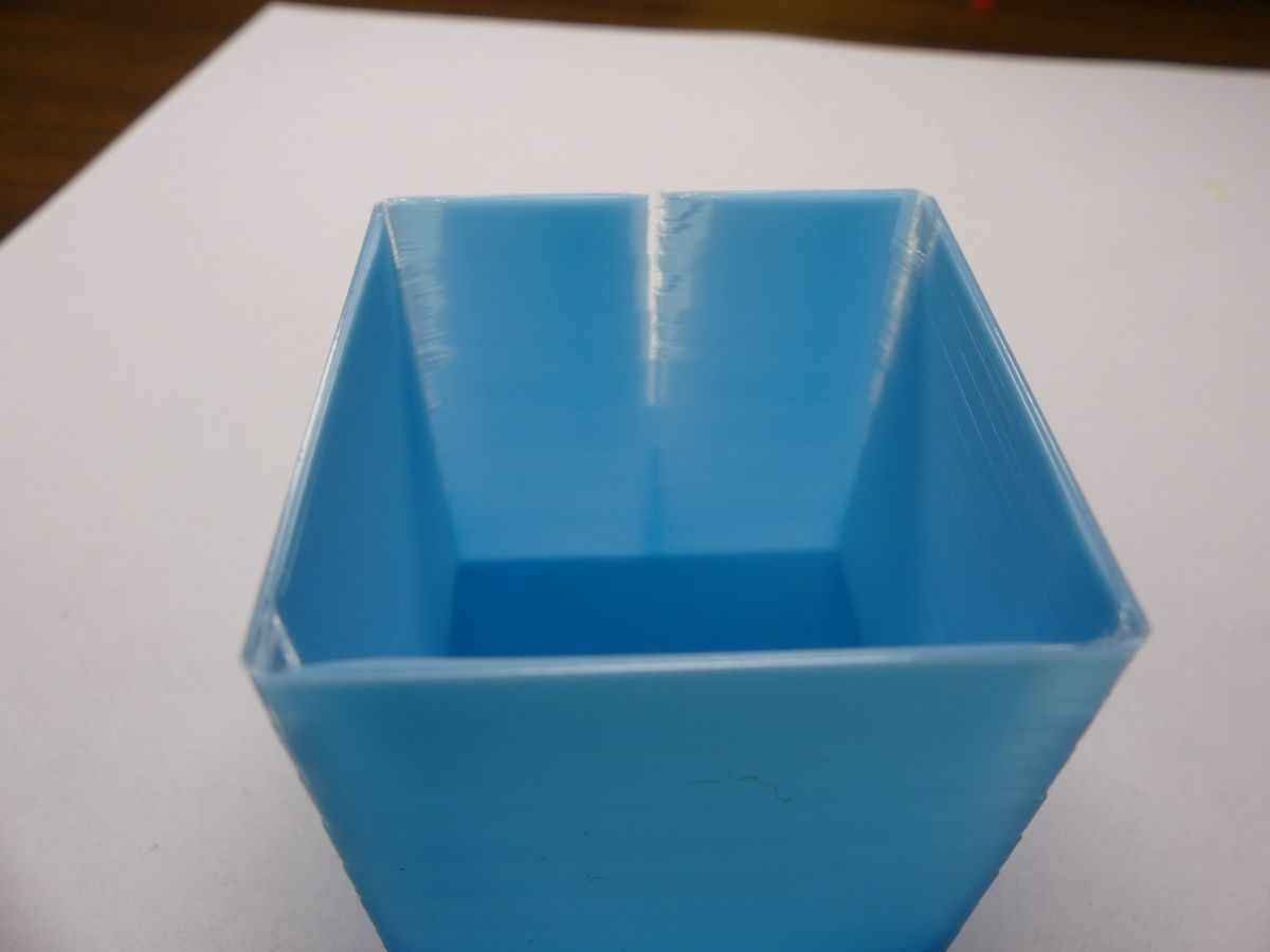
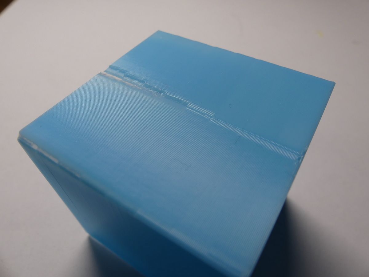
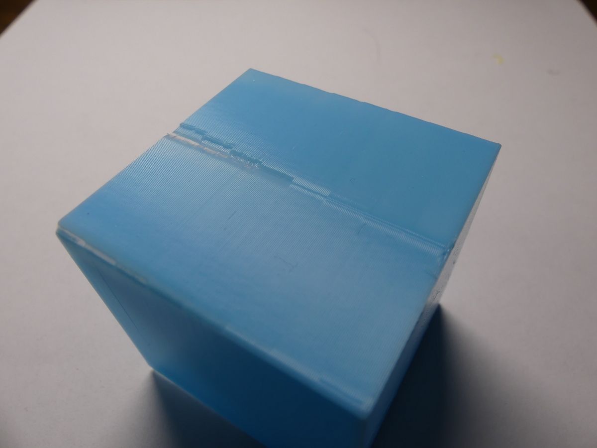
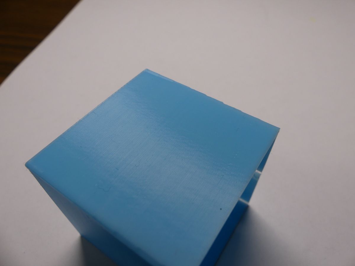
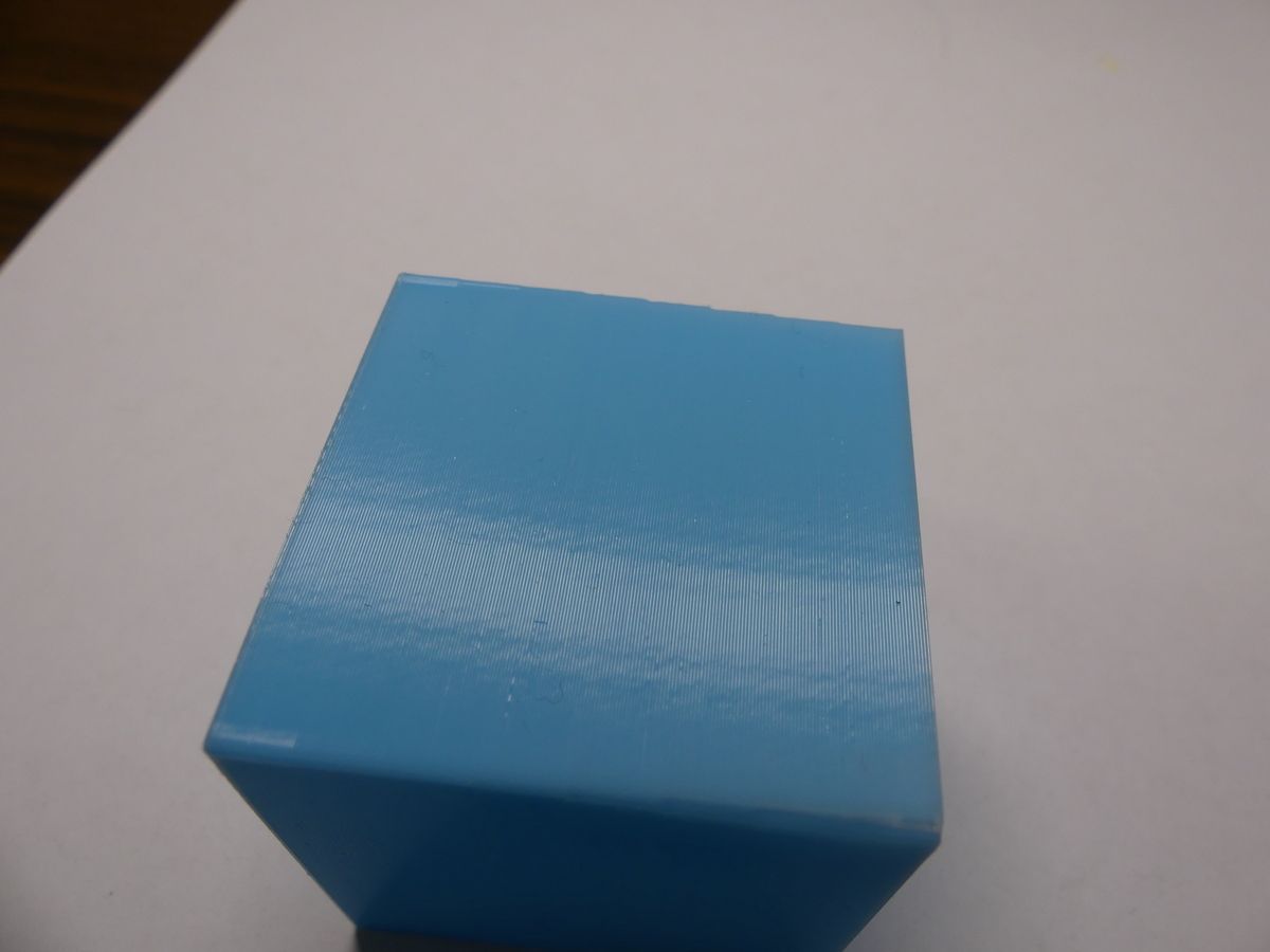
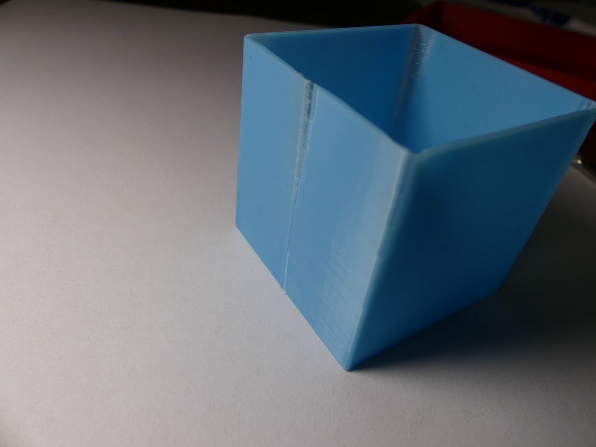
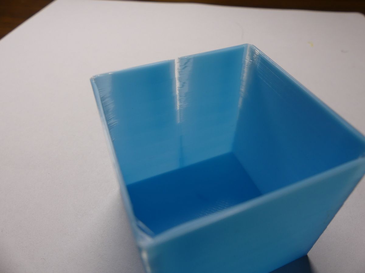
Below are some pictures. This is a 40x40x40mm cube, 2 layers bottom, 2 perimeters, 0 layers top, 0 infill, Prusa Slicer with this before-layers conditional gcode:
; 0.2mm layer, 8 bands 5mm each, total height 40mm
{if layer_num== 1}M572 D0 S0.0
{elsif layer_num== 25}M572 D0 S0.05
{elsif layer_num== 50}M572 D0 S0.10
{elsif layer_num== 75}M572 D0 S0.15
{elsif layer_num== 100}M572 D0 S0.20
{elsif layer_num== 125}M572 D0 S0.25
{elsif layer_num== 150}M572 D0 S0.30
{elsif layer_num== 175}M572 D0 S0.35
{endif}
The optimal band is the 4th from the bottom at PA=0.15. This is with a BMG+Titan direct extruder.
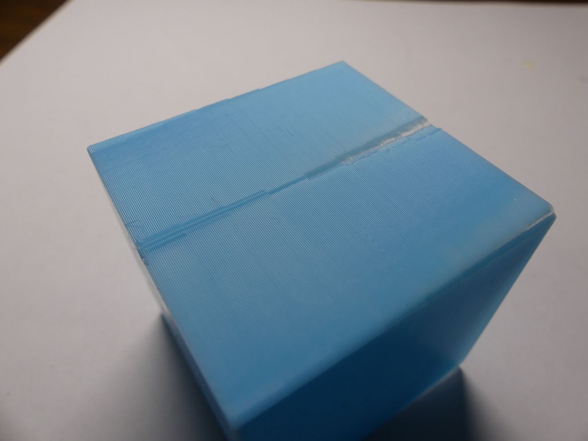
-
@zapta That's perfect. Thank you. I'll update the PA doc.
-
@Phaedrux said in Pressure advance doesn't affect the printed model:
I'll update the PA doc.
Thanks Phaedrux.