Z-probe already triggered ...
-
I am building my delta printer with a Duet WiFi and Smart Effector v1.3. When it powers on I do not see any flashing on the LED. I have checked the voltage at the wiring on the effector, and there is 3.24V between pin 6 and 8. Duet web control shows Z-Probe at 1000. G32 and G30 say Z-Probe already trigged at start of probing. I do not have the part cooling or hot end fan running, neither the heated bed.
Any recommendations or other information I should provide?
Thanks.
-
@roguebyte Please send M115 to your Duet, and post the response. This will show the firmware version you are on. Also please post your config.g file.
Most problems are either configuration, or wiring. Check continuity of the wires, and check with the wiring diagram where you have plugged them in. Maybe a quick picture of the Effector wiring, and of the Duet showing where the wiring is connected would also help.
Ian
-
Thanks for reading and assisting.
Here's the information requested.
M115
FIRMWARE_NAME: RepRapFirmware for Duet 2 WiFi/Ethernet FIRMWARE_VERSION: 2.05.1 ELECTRONICS: Duet WiFi 1.02 or later FIRMWARE_DATE: 2020-02-09b1

; Configuration file for Duet WiFi (firmware version 2.03)
; executed by the firmware on start-up
;
; generated by RepRapFirmware Configuration Tool v2.1.8 on Mon Mar 30 2020 22:28:21 GMT-0500 (CDT)

; General preferences
G90                                         ; send absolute coordinates...
M83                                         ; ...but relative extruder moves
M550 P"Pythagoras"                          ; set printer name
M665 R172 L304.11 B110 H315                 ; Set delta radius, diagonal rod length, printable radius and homed height
M666 X0 Y0 Z0                               ; put your endstop adjustments here, or let auto calibration find them

; Network
M552 S1                                     ; enable network
M586 P0 S1                                  ; enable HTTP
M586 P1 S0                                  ; disable FTP
M586 P2 S0                                  ; disable Telnet

; Drives
M569 P0 S1                                  ; physical drive 0 goes forwards
M569 P1 S1                                  ; physical drive 1 goes forwards
M569 P2 S1                                  ; physical drive 2 goes forwards
M569 P3 S1                                  ; physical drive 3 goes forwards
M584 X0 Y1 Z2 E3                            ; set drive mapping
M350 X256 Y256 Z256 I0                      ; configure microstepping without interpolation
M350 E16 I1                                 ; configure microstepping with interpolation
M92 X3200.00 Y3200.00 Z3200.00 E2700.00     ; set steps per mm
M566 X1200.00 Y1200.00 Z1200.00 E1200.00    ; set maximum instantaneous speed changes (mm/min)
M203 X18000.00 Y18000.00 Z18000.00 E1200.00 ; set maximum speeds (mm/min)
M201 X1000.00 Y1000.00 Z1000.00 E1000.00    ; set accelerations (mm/s^2)
M906 X1000 Y1000 Z1000 E800 I30             ; set motor currents (mA) and motor idle factor in per cent
M84 S30                                     ; Set idle timeout

; Axis Limits
M208 Z0 S1                                  ; set minimum Z

; Endstops
M574 X2 Y2 Z2 S1                            ; set active high endstops

; Z-Probe
M558 P5 R0.4 H5 F1200 T6000                 ; set Z probe type to effector and the dive height + speeds
G31 P100 X0 Y0 Z0.1                         ; set Z probe trigger value, offset and trigger height
M557 R85 S20                                ; define mesh grid

; Heaters
M305 P0 T100000 B4138 R4700                 ; set thermistor + ADC parameters for heater 0
M143 H0 S120                                ; set temperature limit for heater 0 to 120C
M305 P1 T100000 B4138 R4700                 ; set thermistor + ADC parameters for heater 1
M143 H1 S280                                ; set temperature limit for heater 1 to 280C

; Fans
M106 P0 S0 I0 F500 H-1                      ; set fan 0 value, PWM signal inversion and frequency. Thermostatic control is turned off

; Tools
M563 P0 S"Effector" D0 H1 F0                ; define tool 0
G10 P0 X0 Y0 Z0                             ; set tool 0 axis offsets
G10 P0 R0 S0                                ; set initial tool 0 active and standby temperatures to 0C

; Custom settings are not defined
Please disregard the wiring of the power connectors in the background of the effector picture, I know I have to fix this.
And as I stated before, I can read 3.24V between pins 6 and 8 off the wired pins on the 8-pin molex.

-
Wiring looks correct in the photos. When you measure voltage, are you measuring the pins on the board (carefully!) from below, with the connector plugged in?
It should at least self test as it powers up.
-
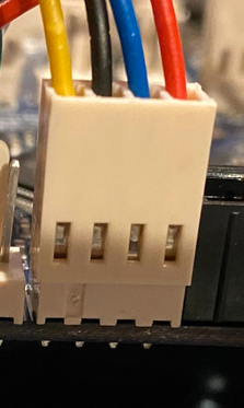
@roguebyte That looks to me like the Black Earth wire isn't seated in the plug at the Effector end which if I am right would explain why it doesn't appear to power up.
Would check the the pin is inserted fully into the shell and locked in place!
HTH
Doug
-
@roguebyte Looks like the blue wire connection to the board has got bent back too:

Ian
-
Thanks everyone. Turns out it was my faulty crimping. I cut off all the wires on the 8-pin Molex and crimped them again. Admittedly these were my first crimps in this project and weren’t my best. LED flashes after power up and successfully ran auto-calibration.
Just have to fix the crimps on that power connector and I’ll be testing the hot end and extruder.
-
@roguebyte one of those instances where a picture is worth a thousand words!
Ian
-
Glad you got it sorted!