Navigation

    Duet3D Logo

    Duet3D

    • Register
    • Login
    • Search
    • Categories
    • Tags
    • Documentation
    • Order

    topic_unsolved Dual Z-Probe at IDEX System

    General Discussion
    5
    21
    192
    Loading More Posts
    • Oldest to Newest
    • Newest to Oldest
    • Most Votes
    Reply
    • Reply as topic
    Log in to reply
    This topic has been deleted. Only users with topic management privileges can see it.
    • CR3D
      CR3D last edited by

      Hi everyone...

      I am currently building a large format 3D printer with IDEX system.
      I've already set up an IDEX, but now I want to try something new.

      I use the Orion Piezo sensor as a Z-probe. this works very well in other printers.
      and now my question.

      Can I also connect a piezo sensor as a z-probe or other sensor on the second toolhead (i.e. U-axis)? so that I measure both toolheads beforehand and save the offsets. That would save a lot of adjustment work.

      if so, how would you implement this in the firmware?

      Many thanks to all of you!

      Regards Christian (CR-3D)

      1 Reply Last reply Reply Quote 0
      • CR3D
        CR3D last edited by

        Any Ideas?

        1 Reply Last reply Reply Quote 0
        • sebkritikel
          sebkritikel last edited by

          I run an IDEX system, but I have not put any thought into attaching a probe to the second hotend. I have my BLTouch on my X carriage, with the U carriage being the second hotend.

          https://duet3d.dozuki.com/Wiki/ConfiguringMultipleIndependentXcarriagesCartesian

          "If you home Z using a Z probe, then that probe should be mounted on the X carriage..."

          Ignoring if the firmware could support two probes for two different hotends, here is how I imagine the calibration procedure will go

          1. Determine X, Y and Z offsets for probe0 on Carriage X
          2. Determine X, Y, and Z offsets for probe1 on Carriage U
          3. Determine the X and Y tool offset for Carriage U

          Why step three? Well when working with IDEX systems, I find its best to assume no tool offset on the X carriage. While the X and U carriages (typically) share the same Y axis, you will have some X and Y offset in the U carriage due to tolerance stackup in assembly - the parts for the X and U carriage will not be made perfectly the same. You'll essentially have to zero the U carriage X and Y to a predetermined point established by the X carriage (e.g. X0, Y0 relative to the X carriage).

          If you change a nozzle on any hotend, you'll probably need to do all three (specifically Z offsets).

          With the probe only on the X axis, the process looks like

          1. Determine X, Y and Z offsets for probe0 on Carriage X
          2. Determine the X, Y and Z tool offset for Carriage U

          Again, unsure if there is a mechanism in the firmware, or with conditional gcode, object model, etc, that can aid in two probes.

          1 Reply Last reply Reply Quote 0
          • Phaedrux
            Phaedrux Moderator last edited by

            RRF3 has support for multiple probes, how that would relate to the coordinate system I am not sure.

            1 Reply Last reply Reply Quote 0
            • CR3D
              CR3D last edited by

              @Phaedrux said in Dual Z-Probe at IDEX System:

              RRF3 has support for multiple probes, how that would relate to the coordinate system I am not sure.

              Ok thank you for your answers!

              @sebkritikel: Do you think I have to calibrate also the X and Y offset after a nozzle change?

              1 Reply Last reply Reply Quote 0
              • dc42
                dc42 administrators last edited by

                You can use a G30 S-2 command to probe the bed and automatically adjust the tool Z offset to make the stop height equal to the trigger height. Obviously you need to make sure that only the nozzle of the active tool can contact the bed, for example by having the other tool off the edge of the bed when you probe.

                To do ditto prints or mirror prints, you need to have both nozzles at the same height.

                CR3D 1 Reply Last reply Reply Quote 0
                • CR3D
                  CR3D @dc42 last edited by

                  @dc42

                  Ok fantastic! 🙂

                  If the build is finished the next weeks I will test it and report here 😉

                  Thank you!

                  1 Reply Last reply Reply Quote 0
                  • CR3D
                    CR3D last edited by

                    This post is deleted!
                    1 Reply Last reply Reply Quote 0
                    • CR3D
                      CR3D last edited by

                      Ok now I want to configurate the Dual Z-Probe at my IDEX with Duet3 V1.0 and RRF 3.1.1

                      Where do I have to define the second Z sample with the K parameter? In the config?

                      How do I then trigger a measurement process with the second Z-sample (mounted on the second printhead)?

                      1 Reply Last reply Reply Quote 0
                      • Phaedrux
                        Phaedrux Moderator last edited by

                        Check these docs, particularly for the K parameter to reference the different probes.

                        https://duet3d.dozuki.com/Wiki/Gcode#Section_G30_Single_Z_Probe
                        https://duet3d.dozuki.com/Wiki/Gcode#Section_G31_Set_or_Report_Current_Probe_status
                        https://duet3d.dozuki.com/Wiki/Gcode#Section_M558_in_RepRapFirmware_Num_3

                        CR3D 1 Reply Last reply Reply Quote 0
                        • CR3D
                          CR3D @Phaedrux last edited by

                          @Phaedrux

                          Thank you! 🙂

                          I know all three digits of the GCode table, but I just don't know how to implement it.

                          I understood the commands that I need at itself, but not how I select the second probe so that it references it.

                          1 Reply Last reply Reply Quote 0
                          • Phaedrux
                            Phaedrux Moderator last edited by

                            Well if you read the K parameter description of those three commands you'll see how to use each to target your desired probe.

                            You'll need an M558 and G31 for each probe. K0 and K1. Then when you want to probe with G30, specify the probe number with K0 or K1.

                            CR3D 1 Reply Last reply Reply Quote 0
                            • CR3D
                              CR3D @Phaedrux last edited by

                              @Phaedrux

                              Ok i configured it like that:

                              Config.g

                              ; Z-Probe (Piezo)
                              M558 P5 I1 C"!io3.in" R1.0 K0 H5 F200 T6000 ; Z probe type -> Piezo
                              M558 P5 I1 C"!io4.in" R1.0 K1 H5 F200 T6000 ; Z probe type -> Piezo
                              

                              config-override.g

                              ; Z probe parameters
                              
                              G31 T0 P600 X0.0 Y0.0 Z-0.045
                              G31 T1 P600 X0.0 Y0.0 Z-0.045
                              

                              Homez.g

                              ; homez.g
                              ; called to home the Z axis
                              ;
                              M106 P0 S0
                              G90                   ; absolute positioning
                              G1 X220 Y200 U600 F8000    ; first bed probe point -> move X to the middle of the Bed, U outside and home Z
                              T0
                              G30 S-2 K0
                              G1 X0 Y200 U300 F8000    ; first bed probe point -> move X outside, U to the middle of the Bed and home Z
                              T1
                              G30 S-2 K1
                              

                              The normal homing with Tool 0 works fine, but if he references Tool 1 he will infinitely move the Z-axis in the positive direction ...

                              I also get not the right values from the second probe:

                              b53b8c48-6f12-4487-b37e-143f9e059008-image.png

                              Any ideas?

                              Phaedrux 1 Reply Last reply Reply Quote 0
                              • Phaedrux
                                Phaedrux Moderator @CR3D last edited by

                                @CR3D said in Dual Z-Probe at IDEX System:

                                config-override.g
                                ; Z probe parameters G31 T0 P600 X0.0 Y0.0 Z-0.045 G31 T1 P600 X0.0 Y0.0 Z-0.045

                                I don't think you'll be able to use config-override.g for the G31 for this purpose because it doesn't have the K value. According to the wiki entry the T value is not used in RRF3. So put those G31 entries in config.g and change the T0 and T1 to K0 and K1.

                                The behaviour you're seeing makes sense because the first probe is k0 by default.

                                CR3D 1 Reply Last reply Reply Quote 0
                                • CR3D
                                  CR3D @Phaedrux last edited by

                                  @Phaedrux Thank you! 🙂 Ok i put the G31 commands into the config.g

                                  ; Z-Probe (Piezo)
                                  M558 P5 I1 C"!io3.in" R1.0 K0 H5 F200 T6000 ; Z probe type -> Piezo
                                  M558 P5 I1 C"!io4.in" R1.0 K1 H5 F200 T6000 ; Z probe type -> Piezo
                                  
                                  G31 K0 P600 X0.0 Y0.0 Z-0.045
                                  G31 K1 P600 X0.0 Y0.0 Z-0.045
                                  

                                  Homeall.g

                                  G90                   ; absolute positioning
                                  G1 X220 Y200 U600 F8000    ; first bed probe point -> move X to the middle of the Bed, U outside and home Z
                                  T0
                                  G30 S-2 K0 
                                  G1 X0 Y200 U300 F8000    ; first bed probe point -> move X outside, U to the middle of the Bed and home Z
                                  T1
                                  G30 S-2 K1
                                  

                                  but unfortunately he still does not reference sample 2 correctly ... the print bed moves towards max ....

                                  dc42 1 Reply Last reply Reply Quote 0
                                  • Phaedrux
                                    Phaedrux Moderator last edited by

                                    I will have to run this past @dc42 to see what we're missing.

                                    1 Reply Last reply Reply Quote 0
                                    • CR3D
                                      CR3D last edited by

                                      I hope @dc42 can help me!

                                      It is not running till yet 😞

                                      1 Reply Last reply Reply Quote 0
                                      • dc42
                                        dc42 administrators @CR3D last edited by

                                        @CR3D said in Dual Z-Probe at IDEX System:

                                        but unfortunately he still does not reference sample 2 correctly ... the print bed moves towards max ....

                                        Please explain exactly what you mean:

                                        • Does a G30 K1 command work correctly?
                                        • Does a G30 K2 command work correctly? If not, what does it do?

                                        Please post your complete config.g and config-override.g files as they now are.

                                        CR3D 1 Reply Last reply Reply Quote 0
                                        • CR3D
                                          CR3D @dc42 last edited by

                                          @dc42

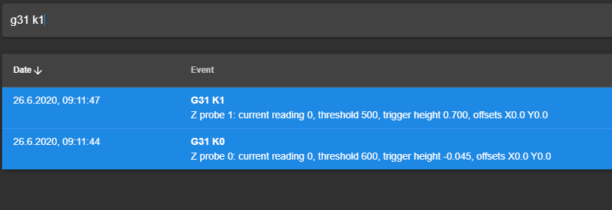
                                          When I run G30 K0 (for Probe 0 at the X-Carriage) in the console after homing X, Y and U manually it works

                                          When I run G30 K1 (for Probe 1 at the U-Carriage) I also have to trigger the Probe at the X-Carriage and not at the U-Carriage.

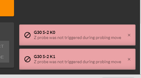
                                          When I run G30 S-2 K0 and G30 S-2 K1 -> the Z-Axis does not move and the error message pop up...

                                          1787baf4-88d1-411d-bdd2-7046fc41d1a1-image.png

                                          When I run G28 ... the X, Y and U Axis homes correctly, then the X-Carriage moves to the middle of the print bed -> probing (Error Message like above), then the U-Axis moves into the middle (Error Message like above)
                                          and then the Z-Axis moves with highspeed into the max direction (away from the Z-Probe)

                                          Here are my config files:

                                          Config.g

                                          ; Configuration file for Duet 3 (firmware version 3)
                                          
                                          
                                          ; General preferences
                                          G90            ; send absolute coordinates...
                                          M82            ; and absolute extruder moves
                                          M550 P"I444-S" ; set printer name
                                          
                                          ; Network
                                          M552 S1        ; enable network 
                                          M586 P0 S1     ; enable HTTP
                                          M586 P1 S0     ; disable FTP
                                          M586 P2 S0     ; disable Telnet
                                          
                                          ; Drives
                                          
                                          M569 P0.0 S1   ; physical drive 0.0 goes forwards Y0
                                          M569 P0.1 S0   ; physical drive 0.1 goes forwards Y1
                                          M569 P0.2 S0   ; physical drive 0.2 goes forwards X
                                          M569 P0.3 S0   ; physical drive 0.3 goes forwards X1 (U)
                                          M569 P0.4 S0   ; physical drive 0.4 goes backwards E0
                                          M569 P0.5 S0   ; physical drive 0.5 goes backwards E1
                                          
                                          M569 P1.0 S1   ; physical drive 1.0 goes forwards Z0
                                          M569 P1.1 S1   ; physical drive 1.0 goes backwards Z1
                                          M569 P1.2 S1   ; physical drive 1.0 goes forwards Z2
                                          
                                          
                                          ;New Mapping
                                          M584 X0.2 Y0.0:0.1 U0.3 Z1.0:1.1:1.2 E0.4:0.5  ; set drive mapping
                                          
                                          M350 X16 Y16 U16 Z16 E16:16 I1  ; configure microstepping 
                                          M92 X80.00 Y35.56 U80 Z1600 E415:415 ;set steps per mm
                                          M566 X900 Y900 U900 Z12 E120:120   ;set maximum instantaneous speed changes (mm/min)
                                          M203 X60000 Y60000 U60000 Z1000 E9000:9000      ;set maximum speeds (mm/min)
                                          M201 X2000 Y2000 U2000 Z200 E1000:1000            ;set accelerations (mm/s^2)
                                          M906 X1400 Y4200 U1200 Z1500 E1000:1000 I30  ;set motor currents (mA)
                                          M84 S30             		    ; Set idle timeout
                                          
                                          ; Axis Limits
                                          M208 X0 Y0 U0 Z0 S1   		    ; set axis minima
                                          M208 X460 Y500 U460 Z420 S0         ; set axis maxima
                                          
                                          ; Endstops
                                          M574 X1 S1 P"!io1.in" ; active-high endstop for low end on X via pin io0.in
                                          M574 U2 S1 P"!io0.in" ; active-high endstop for high end on U via pin 1.io1.in
                                          M574 Y2 S1 P"!io2.in" ; active-high endstop for high end on Y via pin 1.io2.in
                                          
                                          
                                          ; Z-Probe 
                                          ;M558 P5 C"^!io5.in" H1 F500 T12000 ; Z probe type -> Induktiv
                                          ;G31 P100 X0.0 Y0.0 Z2.0
                                          
                                          M558 P5 C"!io3.in" R1.0 K0 H5 F200 T6000 ; Z probe type -> Piezo
                                          M558 P5 C"!io4.in" R1.0 K1 H5 F200 T6000 ; Z probe type -> Piezo
                                          G31 K0 P100 X0.0 Y0.0 Z-0.30
                                          G31 K1 P100 X0.0 Y0.0 Z-0.30
                                          
                                          M557 X50:410 Y00:340 P04:04      ; define mesh grid
                                          
                                          ; Heaters
                                          M308 S0 P"temp0" Y"thermistor" T100000 B4092          ; configure sensor 0 as thermistor on pin temp0
                                          M950 H0 C"out0" T0                                    ; create bed heater output on out0 and map it to sensor 0
                                          M307 H0 B0 S1.00                                      ; disable bang-bang mode for the bed heater and set PWM limit
                                          M140 H0                                               ; map heated bed to heater 0
                                          M143 H0 S120                                          ; set temperature limit for heater 0 to 120C
                                          
                                          M308 S1 P"temp1" Y"thermistor" T100000 B4725 C7.06e-8 ; configure sensor 1 as thermistor on pin temp1
                                          M950 H1 C"out1" T1                                    ; create nozzle heater output on out1 and map it to sensor 1
                                          M307 H1 B0 S1.00                                      ; disable bang-bang mode for heater  and set PWM limit
                                          
                                          M308 S2 P"temp2" Y"thermistor" T100000 B4725 C7.06e-8 ; configure sensor 2 as thermistor on pin temp2
                                          M950 H2 C"out2" T2                                    ; create nozzle heater output on out2 and map it to sensor 2
                                          M307 H2 B0 S1.00                                      ; disable bang-bang mode for heater  and set PWM limit
                                          
                                          ; Fans
                                          
                                          M950 F0 C"out4"                                   ; create fan 2 on pin out4 and set its frequency
                                          M106 P0 S0 H-1                                        ; set fan 2 value. Thermostatic control is turned off
                                          M950 F1 C"out5"                                  ; create fan 3 on pin out5 and set its frequency
                                          M106 P1 S1 H2:1 T50                                   ; set fan 3 value. Thermostatic control is turned off
                                          
                                          ; Tools
                                          M563 P0 S"Links" D0 H1 F0:2  ; define tool 0
                                          G10 P0 X0 Y0 Z0 S0 R0        ; set tool 0 axis offsets
                                          G10 P0 R0 S0                 ; active and standby temperatures 
                                          M563 P1 S"Rechts" D1 H2 X3 F1:3   ; define tool 1
                                          G10 P1 Y0 U0 Z0 S0 R0        ; set tool 1 axis offsets
                                          G10 P1 R0 S0                 ; active and standby temperatures 


                                          ; Custom settings are not defined
                                          
                                          ; Open Door Switch
                                          M581 T0 C"1.io3.in"  S0 C0		;trigger #2 (calls trigger0 -> Emergency-Stop)
                                          M582 T0
                                          
                                          ; LEDs
                                          ; Farbe Blue
                                          M950 F2 C"out3" Q500  ; create fan 3 on pin out5 and set its frequency
                                          M106 P2 S125     ;set fan 3 value. Thermostatic control is turned off
                                          ; Farbe Red
                                          M950 F3 C"1.out0" Q500  ; create fan 3 on pin out5 and set its frequency
                                          M106 P3 S0     ;set fan 3 value. Thermostatic control is turned off
                                          ; Farbe Green
                                          M950 F4 C"1.out1" Q500  ; create fan 3 on pin out5 and set its frequency
                                          M106 P4 S150     ;set fan 3 value. Thermostatic control is turned off
                                          ; Farbe White
                                          M950 F5 C"1.out2" Q500  ; create fan 3 on pin out5 and set its frequency
                                          M106 P5 S0     ;set fan 3 value. Thermostatic control is turned off
                                          
                                          
                                          ; Miscellaneous
                                          
                                          M501          ; load saved parameters from non-volatile memory
                                          
                                          T0            ; select first tool
                                          
                                          M572 D0 S0.03
                                          

                                          Config-override.g

                                          ; config-override.g file generated in response to M500
                                          ; This is a system-generated file - do not edit
                                          ; Heater model parameters
                                          M307 H0 A106.1 C65.0 D3.4 S1.00 V24.1 B0
                                          M307 H1 A1014.5 C333.6 D4.6 S1.00 V24.1 B0
                                          M307 H2 A340.0 C140.0 D5.5 S1.00 V0.0 B0
                                          ; Workplace coordinates
                                          G10 L2 P1 X0.00 Y0.00 Z0.00 U0.00
                                          G10 L2 P2 X0.00 Y0.00 Z0.00 U0.00
                                          G10 L2 P3 X0.00 Y0.00 Z0.00 U0.00
                                          G10 L2 P4 X0.00 Y0.00 Z0.00 U0.00
                                          G10 L2 P5 X0.00 Y0.00 Z0.00 U0.00
                                          G10 L2 P6 X0.00 Y0.00 Z0.00 U0.00
                                          G10 L2 P7 X0.00 Y0.00 Z0.00 U0.00
                                          G10 L2 P8 X0.00 Y0.00 Z0.00 U0.00
                                          G10 L2 P9 X0.00 Y0.00 Z0.00 U0.00
                                          

                                          Homeall.g

                                          ; homeall.g
                                          ; called to home all axes
                                          
                                          
                                          M106 P0 S0		; Part cooling Fan off 
                                          G91                    ; relative positioning
                                          
                                          G1 H2 Z10 F6000         ; lift Z relative to current position
                                          G1 H1 X-650 Y550 U650 F5000 ; first pass XYU
                                          G1 H2 X5 Y-5 U-5 F6000     ; go back a few mm
                                          G1 H1 X-20 Y20 U20 F360  ; second pass XY
                                          
                                          
                                          G90                   ; absolute positioning
                                          G1 X270 Y170 U460 F20000    ; first bed probe point -> move X to the middle of the Bed, U outside and home Z
                                          
                                          G30 S-2 K0
                                          
                                          G1 X0 Y170 U200 F20000 
                                          
                                          G30 S-2 K1
                                          
                                          JoergS5 1 Reply Last reply Reply Quote 0
                                          • JoergS5
                                            JoergS5 @CR3D last edited by

                                            @CR3D can you please show your tfree0.g, tfree1.g, tpost0.g and tpost1.g files? You selected T0 in config, after homing the tool is deselected, maybe there is code in the file which is wrong.
                                            "Then use the tfree#.g files (where # is the tool number) to park a tool when you stop using it. To park a tool you could just home it" in https://duet3d.dozuki.com/Wiki/ConfiguringMultipleIndependentXcarriagesCartesian

                                            CR3D 1 Reply Last reply Reply Quote 0
                                            • CR3D
                                              CR3D @JoergS5 last edited by

                                              @JoergS5 said in Dual Z-Probe at IDEX System:

                                              At the moment all toolchange files are completly empty...

                                              This would be the next step if the system is running.... 😞

                                              1 Reply Last reply Reply Quote 0
                                              • First post
                                                Last post
                                              Unless otherwise noted, all forum content is licensed under CC-BY-SA