12v water pump to 24v system problem
-
I'm just about done and was connecting my water pump to the fan06 on my duet3 and a pop up message keeps appearing saying that my board is under powered. I'm using a 450watt 10a psu connected to a wall ouitlet at 120v. I'm also using pin fan09 for my radiator fan, and have the heater and motors connected. I'm using as 24v to 12v power converter for the 12v fan and pump. By the way, they are part of e3d water cooling kit. Heres some screen shots of what I see on my screen and code. Using reprap3.1.1 and have a raspi connected via ribbon cable and micro USB.
-
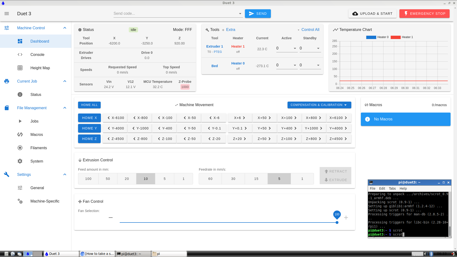
This is when I have everything connected but the pump.
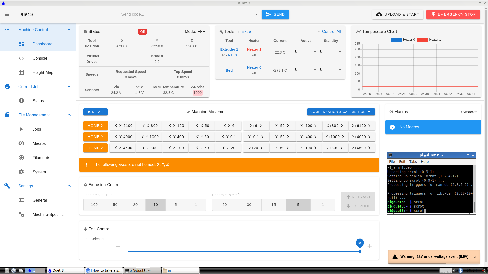
This is when I have the pump connected.
-
; Fans M950 F0 C"out9" Q500 ; create fan 0 on pin out9 and set its frequency M106 P0 S0 H1 T45 ; set fan 0 value. Thermostatic control is turned on M950 F1 C"out6" Q500 ; create fan 1 on pin out6 and set its frequency M106 P1 S1 H1 T45 ; set fan 1 value. Thermostatic control is turned on -
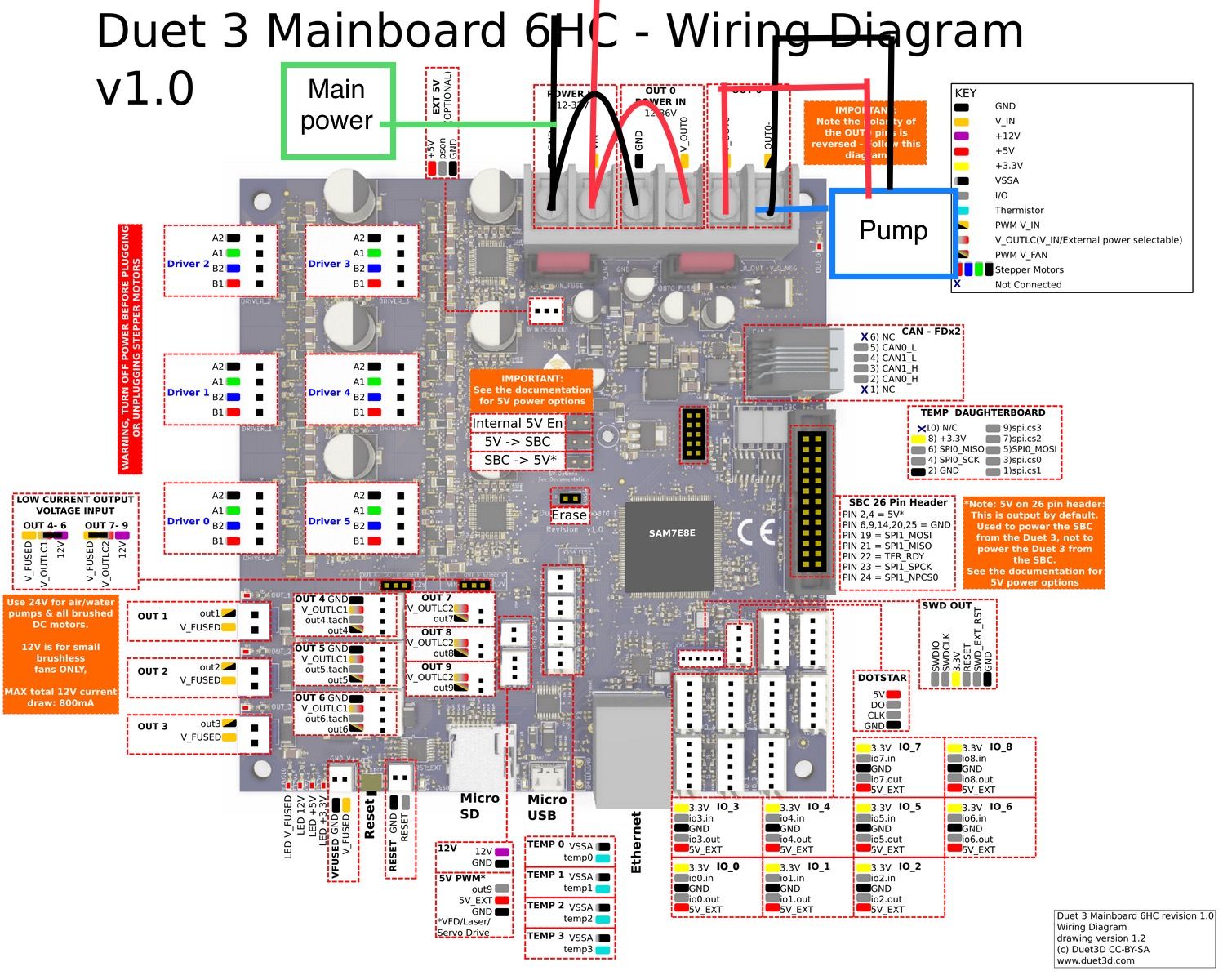
@1997alex you may be above the 800 mA limit if using the out9 with 12V (9.6 W maximum):
see Duet 3 wiring diagram left orange box. From the description of the orange box, it would be IMHO better to connect the pump as 24V and connect the 12V fan somewhere else.
Out4-6 seems to be handled by the switch left, and Out7-9 from switch right, so you could connect 24V pump to one of the left Outs and 12V fan to one of the right and set the switches acccordingly. (but I speak from diagram view, not experience, please recheck my recommendation). I expect the switch left position to be the VIN, so it depends whether your PSU is 12V or 24V. If you use the left switch position with step down from 24V to 12V for the pump because you have a 12V PSU, the maximum mA is not specified in the diagram. The critical point with stepdown is that the current is higher (here doubled) after stepping down and may be too much for the electronics of the Duet3. You could consider upgrading PSU to 24V.
(image upload I get an error, the image is at
https://duet3d.dozuki.com/Wiki/Duet_3_Mainboard_6HC_Wiring_Diagram wiring diagram)Another option is to not use the Out connector, but running the pump with a relais (SSR eg) and control the relais switching on/off with the Duet. And use a dedicated 24V PSU for the pump, which you could use later to upgrade Duet to 24V (next could be the heated bed to be controlled by SSR).
-
Thanks for the quick reply, yes the psu is 24v, sorry should have mentioned that.
-
@1997alex So it should be possible to connect 24V pump to one side (switch set to VIN) and fan 12V to the other (switch set to 12V). I would check that the pump has not more than about 20W (the 24V with 0.8 A).
-
@1997alex said in 12v water pump to 24v system problem:
water pump to the fan06
depending on the type of pump you might need to move this to the heater outputs or add a diode to snubb the back emf of the pump when it turns off?
burshless pump should be fine, but in the off chance its a brushed pump you need to deal with the inductive load.
@JoergS5 said in 12v water pump to 24v system problem:
I would check that the pump has not more than about 20W (the 24V with 0.8 A).
800mA applies to sourcing current from the internal 12v supply only. sourcing current from Vin each output can sink 2.5A.
-
By heater out put you mean the out0? I’m sorry for question, I looked at the diagram and i made a quick drawing of where I would connect the wires. How does that look? Then just change the out 6 from the code to out0? Would that even work. I even tried using the out 1-3 which is rated for 6am and says it’s 5.6 volts under powered compared to before which was 9.8volts.
-
I'm also using the E3D water cooling kit, or rather I was. I have since completely changed my water cooling setup, but I digress.
Initially i ran some tests on the E3D system and it should run just fine under 800mA. And for awhile it did, but then the pump seized up and the little motor in it started to draw 1.2 A and also stopped pumping. once it stopped pumping and drawing 1.2A it kept hitting me with the same error you are experiencing.
To resolve the issue I bought a buck converter on amazon for 20$. for the wiring I simply removed the jumper for Vout 4, 5, and 6 and used a 2 pin dupont connector to take 24V from V_FUSED to the buck converter, then returned the 12V from the buck converter back to V_OUTLC1. For the buck converter ground I simply connected them to the GND pin of the PWR_IN. It works like a charm and I still can use the same output to control when the pump and the rad fan turn on.
-
@baird1fa ok thanks for the help I’ll try connecting it to the outputs you mentioned and see if it wants to work.
-
@baird1fa actually, I have a voltage converter from 24v to 12v but would you be able to draw a quick sketch of what pins i should use on this diagram? sorry for the bother but i really wanna get this right with the least amount of guessing possible. also what jumpers are you refering to? thanks.