Prepare for Surgery!
-
@oliof And now I see it doesn't even have a USB port or any obvious way to input a gcode, so yes, a bit tricky! Could create a Gcode file with just M503 in it, run that, and see if the display spits out anything.
Ian
TronXY X5S with Duet 3 MB6HC and Roto toolboard : Cartesian bed-slinger with Duet 3 Mini 5+ WiFi and 1LC : RRP Fisher Delta v1 with Duet 2 Maestro : Polargraph with Duet 2 WiFi
-
@droftarts exactly, there’s no way to communicate with the board, which is why I’m getting rid of it!
-
@droftarts the people looking at the board actually desoldered the flash chips to dump the firmware to memory. I looked a bit at it with binwalk and radare, but I lack the skills to find anything of value.
-
@oliof I'd love to do that, but how? All I can do is put a micro sd card in the card reader. After that, the screen will show me the gcode files of things I want to print, and that's that?
But if you know a way, I would be HAPPY to give it a try!
Mark
-
@corlissmedia Nothing straightforward you can do here unfortunately.
-
@oliof putting the 5+ isn't exactly straight-forwards, but it sure is fun!
Mark
-
@corlissmedia unless you have some experience in reverse engineering STM binaries I don't think there is much you can do at the time being in the area I am currently fumbling around in the dark.
-
@oliof may someone hand you a headlamp!
-
@corlissmedia I could certainly need one.
-
Alright, I did look at the source code for the Dlion firmware and it predates any UART control. So I guess you will need to measure the reference voltage on the stepper drivers to find out what the used current is.
-
@oliof because?
-
@corlissmedia because the software doesn't govern the current but the little potentiometer setting the reference voltage. As was the case with older)simpler boards where UART control was not available.
-
@oliof I’d love to do that, but I have no idea how.
-
@corlissmedia

This is how far I got today.
-
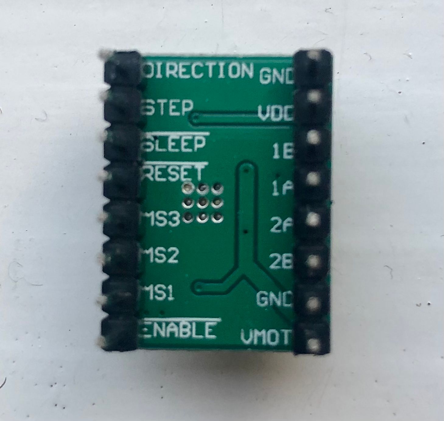
@corlissmedia you will need to power up the old board -- nothing needs to be connected -- and then measure the voltage between ground and the potentiometer. See this guide https://www.inov3d.net/stepper-calibration-tune-your-vref-steps-for-perfect-prints/
depending on the stepper drivers used on the board, there is a specific formula to compute the current that's put out. If you provide a high res photo of the front of the control board we might be able to discern that.
<>RatRig V-Minion Fly Super5Pro RRF<> V-Core 3.1 IDEX k*****r <> RatRig V-Minion SKR 2 Marlin<>
-
@oliof since my recent post was locked, I’ll work on this today. Thank you for helping me.
Mark
-
Does this help?
-
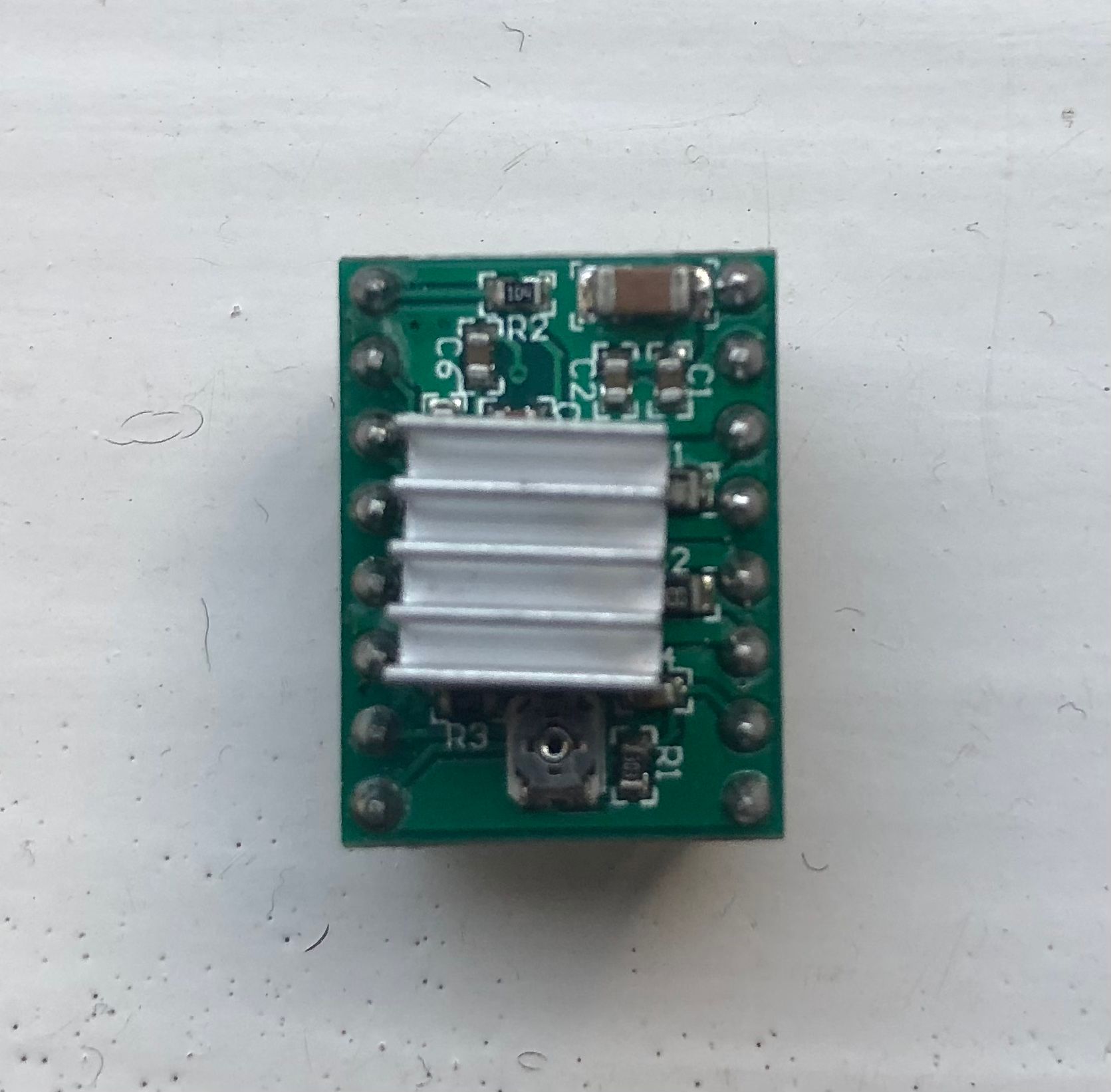
Can you carefully try pulling off the heatsink off of one of the drivers? it would help to see the markings on top of the driver chip. I do expect them to be Allegro 498x chips, but it's always better to know than to guess.
<>RatRig V-Minion Fly Super5Pro RRF<> V-Core 3.1 IDEX k*****r <> RatRig V-Minion SKR 2 Marlin<>
-
@mac To measure the vref (reference voltage) measure the voltage between the potentiometer (circled) and the Ground side of the power input (square), with the power connected.
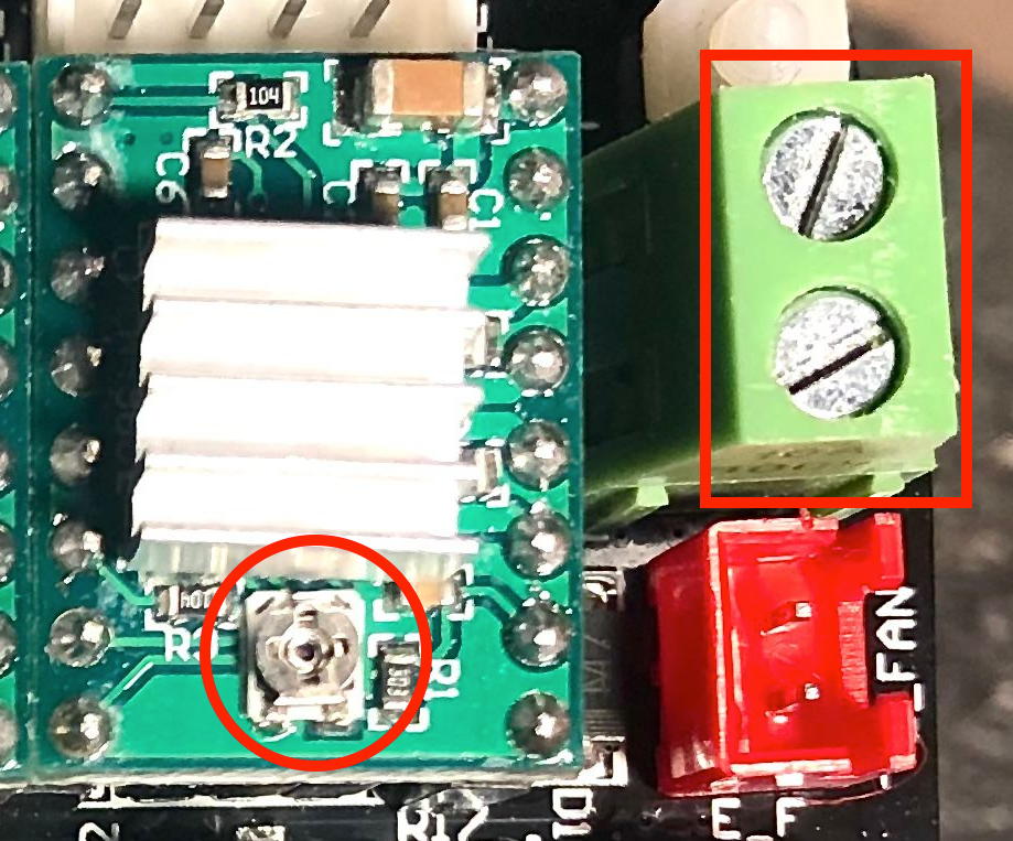
They look like 'Stepstick' drivers. What current the 'vref' relates to will depend on the values of other components, specifically the sense resistors (which are under the heatsink). See https://www.reprap.org/wiki/StepStick
Usually, ITripMAX (effectively max motor current) = VREF / ( 8 x Sense_resistor)
Ian
-
I checked the X, Y, and Z motor connectors this morning to see if the phases were split/installed correctly. As far as I can tell, they were.