Prepare for Surgery!
-
@corlissmedia you will need to power up the old board -- nothing needs to be connected -- and then measure the voltage between ground and the potentiometer. See this guide https://www.inov3d.net/stepper-calibration-tune-your-vref-steps-for-perfect-prints/
depending on the stepper drivers used on the board, there is a specific formula to compute the current that's put out. If you provide a high res photo of the front of the control board we might be able to discern that.
<>RatRig V-Minion Fly Super5Pro RRF<> V-Core 3.1 IDEX k*****r <> RatRig V-Minion SKR 2 Marlin<>
-
@oliof since my recent post was locked, I’ll work on this today. Thank you for helping me.
Mark
-
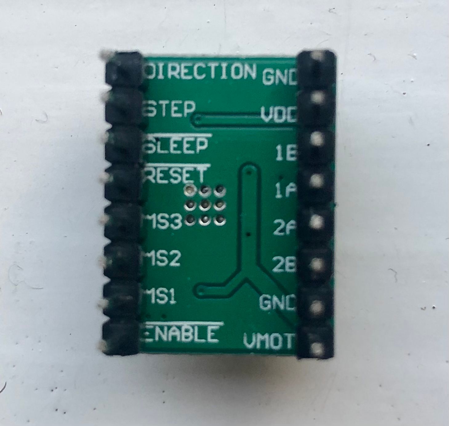
Does this help?
-
Can you carefully try pulling off the heatsink off of one of the drivers? it would help to see the markings on top of the driver chip. I do expect them to be Allegro 498x chips, but it's always better to know than to guess.
<>RatRig V-Minion Fly Super5Pro RRF<> V-Core 3.1 IDEX k*****r <> RatRig V-Minion SKR 2 Marlin<>
-
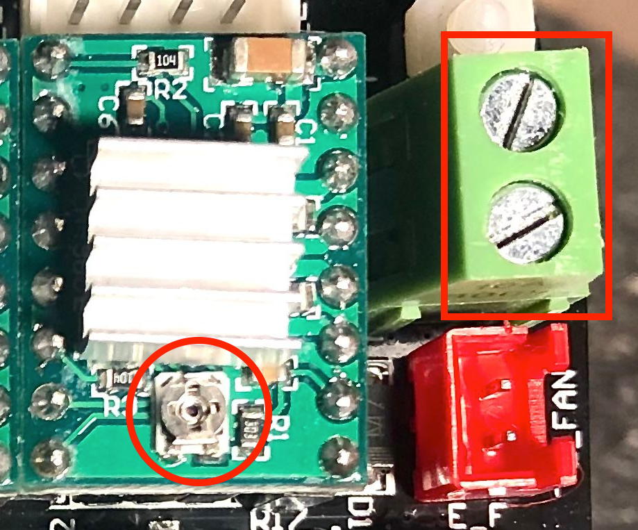
@mac To measure the vref (reference voltage) measure the voltage between the potentiometer (circled) and the Ground side of the power input (square), with the power connected.
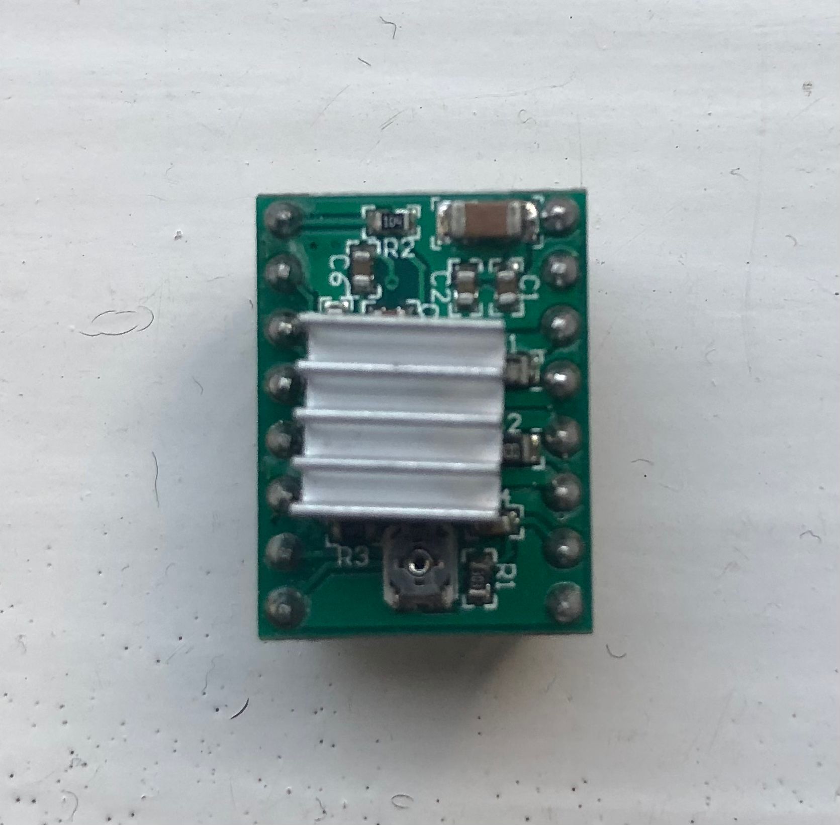
They look like 'Stepstick' drivers. What current the 'vref' relates to will depend on the values of other components, specifically the sense resistors (which are under the heatsink). See https://www.reprap.org/wiki/StepStick
Usually, ITripMAX (effectively max motor current) = VREF / ( 8 x Sense_resistor)
Ian
-
I checked the X, Y, and Z motor connectors this morning to see if the phases were split/installed correctly. As far as I can tell, they were.
-
@mac Need to see under the heatsink that's stuck to the top of the driver. BTW, the layout of the driver looks exactly like a Stepstick. The sense resistors are the two components poking out the side of the heatsink. They are labelled S1 and S2.
Ian
TronXY X5S with Duet 3 MB6HC and Roto toolboard : Cartesian bed-slinger with Duet 3 Mini 5+ WiFi and 1LC : RRP Fisher Delta v1 with Duet 2 Maestro : Polargraph with Duet 2 WiFi
-
@droftarts what does all this mean, guys?
-
@mac pull the heatsink off the driver. It's just held on with some thermally-conductive glue. Also doesn't really help cool the chip underneath; the A4988 chips sink heat through their base, into the copper of the PCB, not through the top of the chip!
Edit: Then look at what number is on the top of the sense resistors, and report back what it is (or post a picture where we can see the numbers). And measure the vref with a voltmeter.
Ian
TronXY X5S with Duet 3 MB6HC and Roto toolboard : Cartesian bed-slinger with Duet 3 Mini 5+ WiFi and 1LC : RRP Fisher Delta v1 with Duet 2 Maestro : Polargraph with Duet 2 WiFi
-
@droftarts okay, off it comes. Picture me to follow.
-
@mac
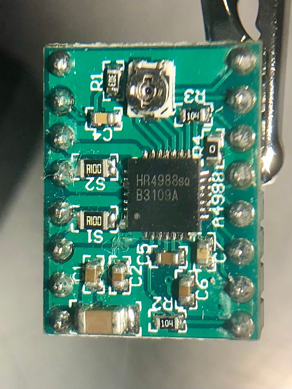
There you go!
-
@droftarts please tell me how to measure the vref.
-
@mac Interesting! The stepstick uses the values that I came up with about 10 years ago, which limits the current to 1.5A max: https://www.reprap.org/wiki/StepStick#Building_stepsticks_with_a_1.5A_limit
The sense resistors (S1 and S2) are 0.1 ohm, so to calculate amps from measured VREF:
A = VREF / 0.8@mac said in Prepare for Surgery!:
please tell me how to measure the vref
I did, a few posts back up https://forum.duet3d.com/post/286301
Ian
TronXY X5S with Duet 3 MB6HC and Roto toolboard : Cartesian bed-slinger with Duet 3 Mini 5+ WiFi and 1LC : RRP Fisher Delta v1 with Duet 2 Maestro : Polargraph with Duet 2 WiFi
-
@droftarts did you design the sanguinololu?
-
@jay_s_uk Not me! I only came up with some values for the Stepstick that were more appropriate for the 3D printers of the time.
Ian
TronXY X5S with Duet 3 MB6HC and Roto toolboard : Cartesian bed-slinger with Duet 3 Mini 5+ WiFi and 1LC : RRP Fisher Delta v1 with Duet 2 Maestro : Polargraph with Duet 2 WiFi
-
@droftarts I think I measured .442 volts divided by 8 is .05525 amps?
-
@mac it’s divide by 0.8, so 0.442 / 0.8 = 0.5525A, or 552.5mA. I think you said your motors are rated for 1A? I’m sure 600mA will be fine.
Ian
TronXY X5S with Duet 3 MB6HC and Roto toolboard : Cartesian bed-slinger with Duet 3 Mini 5+ WiFi and 1LC : RRP Fisher Delta v1 with Duet 2 Maestro : Polargraph with Duet 2 WiFi
-
@droftarts well, that’s good to know, I was thinking these motors are gutless, but apparently not.
So now what! I already know that X, Y, and Z phases are properly split connected to the board. The extruder is wired the same, I’m thinking it’s fine too.
What am I doing wrong?
-
I did the measurement. 0.442 /8 is 552.5 ma? So Ian thinks they’re in spec.
-
@mac the maths check out but make sure to check all the drivers in case one got weird settings.
<>RatRig V-Minion Fly Super5Pro RRF<> V-Core 3.1 IDEX k*****r <> RatRig V-Minion SKR 2 Marlin<>