Is this a problem?
-
@corlissmedia said in Is this a problem?:
I’m guessing there’s a way to see the config g file I created via DWC
See https://docs.duet3d.com/User_manual/Reference/Duet_Web_Control_Manual#system
Ian
TronXY X5S with Duet 3 MB6HC and Roto toolboard : Cartesian bed-slinger with Duet 3 Mini 5+ WiFi and 1LC : RRP Fisher Delta v1 with Duet 2 Maestro : Polargraph with Duet 2 WiFi
-
@droftarts thanks, Ian!
-
@corlissmedia
; Heaters
M308 S0 P"temp0" Y"thermistor" T100000 B3950 ; configure sensor 0 as thermistor on pin temp0
M950 H0 C"out0" T0 ; create bed heater output on out0 and map it to sensor 0
M307 H0 B1 S1.00 ; enable bang-bang mode for the bed heater and set PWM limit
M140 H0 ; map heated bed to heater 0
M143 H0 S120 ; set temperature limit for heater 0 to 120C
M308 S1 P"temp1" Y"thermistor" T100000 B3950 ; configure sensor 1 as thermistor on pin temp1
M950 H1 C"out1" T1 ; create nozzle heater output on out1 and map it to sensor 1
M307 H1 B0 S1.00 ; disable bang-bang mode for heater and set PWM limit
M143 H1 S240 ; set temperature limit for heater 1 to 240CIs this the code that's generating the trouble message?
Mark
-
@corlissmedia Probably, yes, but it's because the board has no temperature sensors plugged in. Hence it sees 'open circuit'.
Ian
TronXY X5S with Duet 3 MB6HC and Roto toolboard : Cartesian bed-slinger with Duet 3 Mini 5+ WiFi and 1LC : RRP Fisher Delta v1 with Duet 2 Maestro : Polargraph with Duet 2 WiFi
-
@droftarts got it, thanks for the confirmation.

X-motor and endstop (to Driver_0 and 105) created.
Mark
-
@corlissmedia more progress
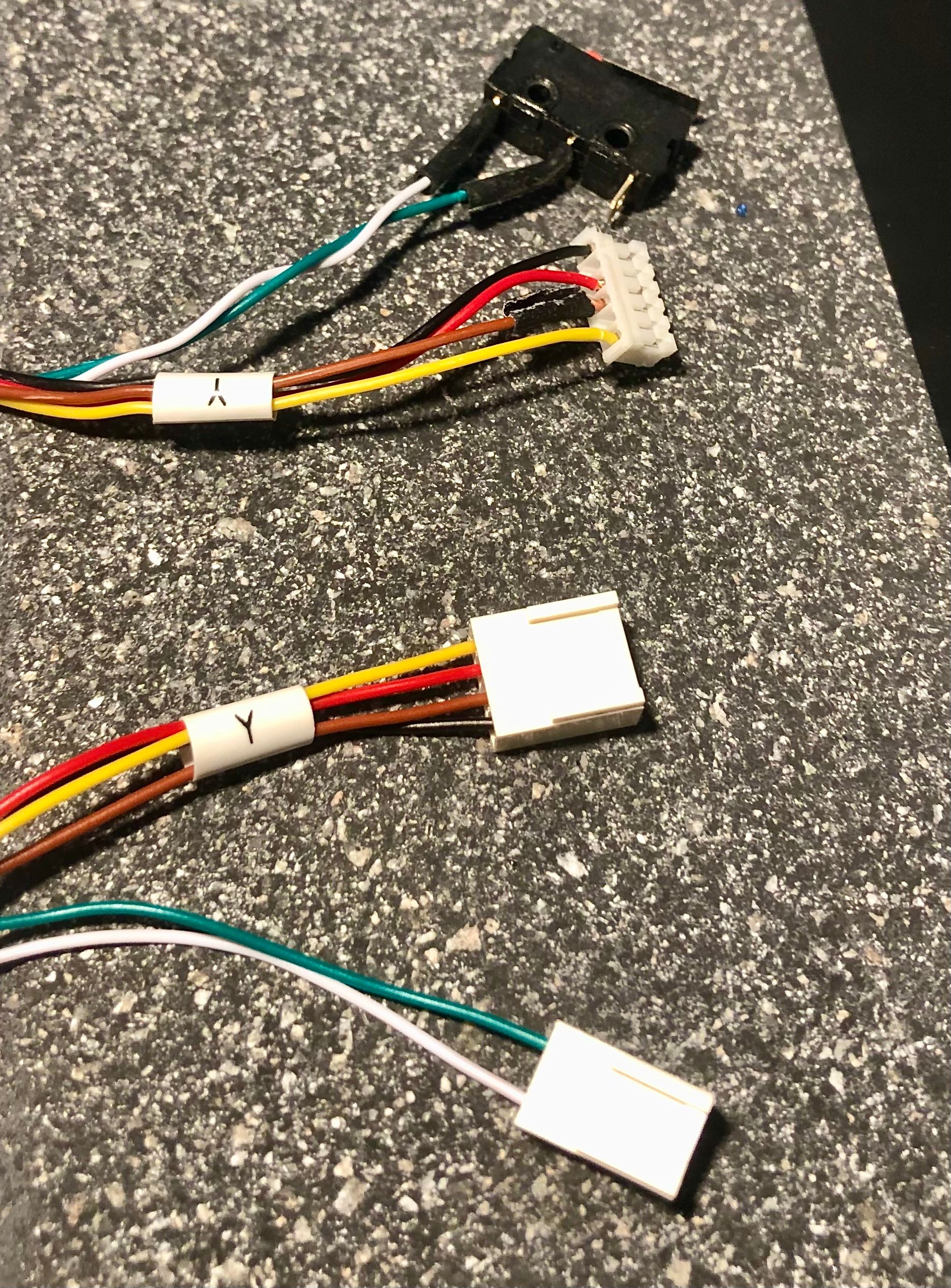
This is the board end at the bottom, and the motor and end stop at the top of the Y motor cable.
-
@corlissmedia it’s usually best to wire micro switches as ‘NC’ as it is less susceptible to noise and leaves the switch in a definite state, rather than floating. This is usually the outer two pins of the micro switch, and marked ‘C’ and ‘NC’. The middle pin is usually marked ‘NO’ for normally open. If you leave them as they are, you will need to invert the logic of the endstop in config.g, by adding
!to the pin name, egM574 Y1 S1 P"!io6.in" ; configure switch-type (e.g. microswitch) endstop for low end on Y via pin io6.inIan
TronXY X5S with Duet 3 MB6HC and Roto toolboard : Cartesian bed-slinger with Duet 3 Mini 5+ WiFi and 1LC : RRP Fisher Delta v1 with Duet 2 Maestro : Polargraph with Duet 2 WiFi
-
@corlissmedia also, as you’re using 3-pin housings for the X and Y endstops, I assume you’re using IO5 and IO6? If so, the cables look correct. If you need to wire a third endstop for Z, you’ll need to use one of the 5 pin IO headers. Check the wiring diagram, as the pin out is different from IO5 and IO6.
Ian
TronXY X5S with Duet 3 MB6HC and Roto toolboard : Cartesian bed-slinger with Duet 3 Mini 5+ WiFi and 1LC : RRP Fisher Delta v1 with Duet 2 Maestro : Polargraph with Duet 2 WiFi
-
This is the info on the back of the board I’m coming from.
-
@droftarts here’s what I did with the Y and Z1 board connectors.


-
@corlissmedia I don’t understand how I should change the 3-pin connectors?
-
@droftarts Okay, so, I don't want to add the !, so what do you propose?
Mark
-
@droftarts well that's good to know!, I did catch that 5-hole socket for 2 wires issue.
-
@corlissmedia if you can solder, desolder the green wire from the center pole of the switch, and solder it to the outside one (where the white wire is not connected to).
-
@oliof so, from what I can tell, all of my end stops are WHITE on the bottom, GREEN in the middle, and BLANK on the top (which is the END of the metal bar). And you're suggesting I move all of my GREEN wires to the top of the endstop / at the end of the metal bar, because this makes them less noisy, correct?
What about the endstop for the X motor, which appears to be reversed from the Y and Z end stops?
Soldering's no problem. Changing these new connectors seems easier than what this printer had before.
Will all of the endstop connectors look the same? I still don't know what the wiring change will do to the new connectors? Will I have a green and a white wire together? Which side of the connector will they be on?
Mark
-
@corlissmedia Yes, I am suggesting to move whatever is in the middle of the endstop to the outer currently unused connector on the endstop. Not only does "normally closed" make them less susceptible to noise, you will also find issues with the wiring more easily.
since an endstop is just a button, it doesn't matter if green goes to one side and white to the other or the other way round. Either way you are connecting Ground and Signal. This is true for both endstop and control board side. Just make sure not to connect to the voltage pins.
I recommend you have a print out of the wiring diagram at hand. I would suggest using IO 5 and 6 for X and Y, using the in and gnd pins (your 3 position plug photos above indicate you did this). For Z you will need to use one of the 5 position IOs, I recommend IO4 (or any but IO0 and IO1 because those have special features you may want to use at a later time).
