6XD I/O >> Issue solved
-
@tecno please clarify what you are asking. Is the PnP output a standard 24V-capabhle NPN or PNP output, or something different? Does the opto isolator you pictured represent one that is in the PnP machine, or one you intend to add, or one already on the 6HC? Why does it have two pins labelled C?
-
-
Anybody care to advise?
-
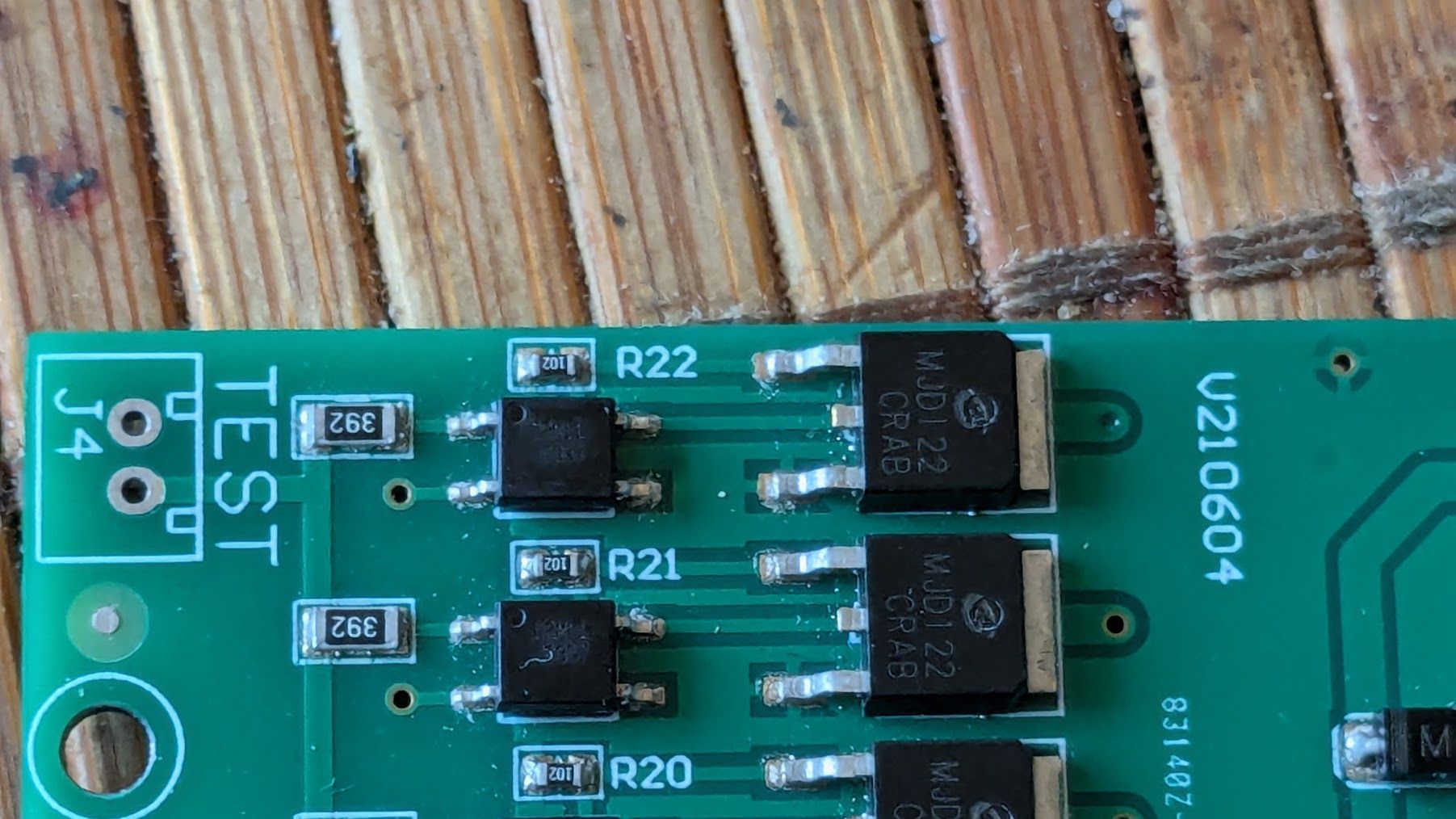
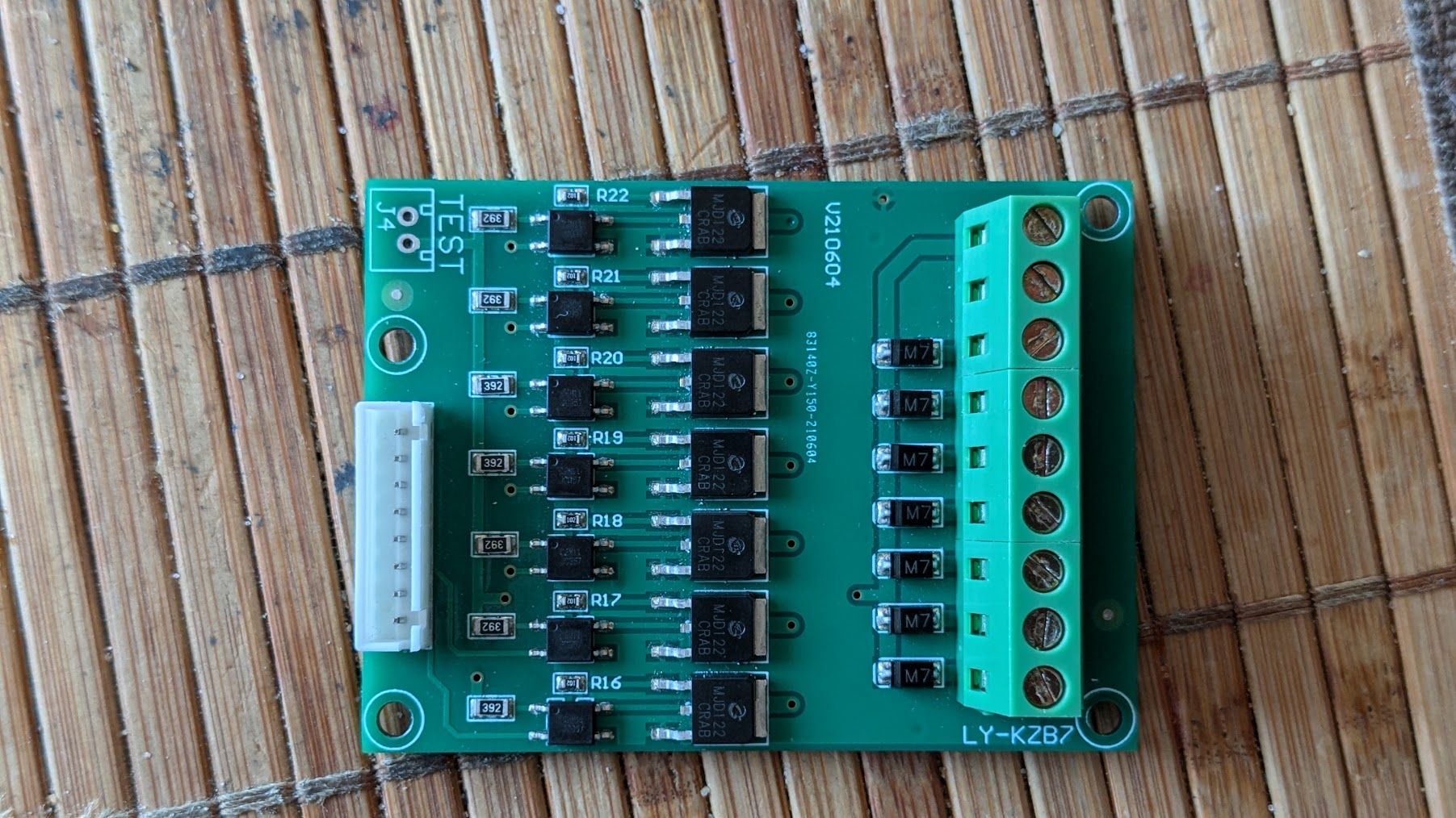
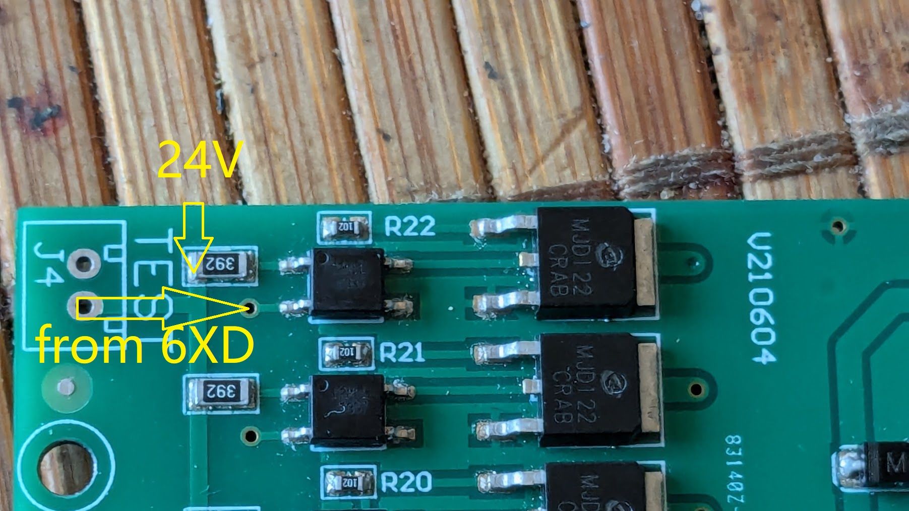
@tecno I need a bit of context. What does this PCB actually do? Does it turn something(s) on and off? Please post an image of the other side of the board, too.
I'd guess it is an output board, as the optocouplers look like they switch MOSFETs, and control whatever is connected on the green headers on the right. There are 8 pins on the white connector, presumably +V on one pin, and 7 pins to switch each of the 7 optocouplers to GND. There are 9 output terminals; presumably +V and GND, plus the 7 outputs from the MOSFETs?
Ian
-
@droftarts
Hi Ian,
You have observed the board correctly. This bord gets outputsignals from controller via the ribboncable.
Controlls nozzle vacuum, pin feeder solenoid Air controll, Xross cursor, LED light and vacuum power.Cheers
Bengt -
-
@tecno If you can look up the product number of the optocouplers (I can't see the part number on them from you pictures), it may be they don't need 24V to turn them on and off. However, if it's wired like this:
There are 8 pins on the white connector, presumably +V on one pin, and 7 pins to switch each of the 7 optocouplers to GND.
and
C = pin 2
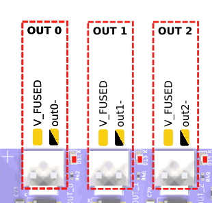
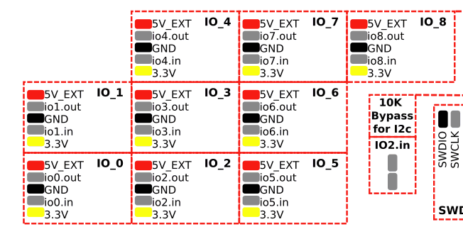
i.e. the R22 optocoupler C pin goes to the second pin down on the connector, the first being +V and shared to the A pin on all Optocouplers (please check if there's continuity between pin 1 and the A pin on each optocoupler with a multimeter), then you need to switch the C pin on each optocoupler to GND, which isn't what the io.out pins do (they output a 3.3V signal). I think you'll need to use the OUT pins for that, which do switch to GND. They should also all be able to cope with 24V.
Ian
-
C2M11
-
@droftarts said in 6XD I/O:
They should also all be able to cope with 24V.
That confirms my question, just wanted to be sure and safe

-
-
These 3 only?
-
@tecno You have the 6x fan outputs as well, 3x 4-pin, 3x 2-pin.
Ian
-
Thanks Ian, appreciated.
-
io1.in is capable to take 24V ??
-
@tecno Yes, but io#.in pins don't switch to GND. They are for reading a voltage input, eg endstop, or digital input, eg communications. See https://docs.duet3d.com/Duet3D_hardware/Duet_3_family/Duet_3_Mainboard_6XD_Hardware_Overview#inputoutput-port-capabilities
Ian
-
@droftarts
OK, will have to sort out my input I/O's and see how they work. -
All limits are OPTO's X, Y, Z1 and Z2 + one more that I can not figure out is Lz
Also Emergency switch did go to old driver.
-
@tecno They can connect to the IO headers. See https://docs.duet3d.com/en/User_manual/Connecting_hardware/Sensors_endstops#h-33v-compatible-optical-endstop
You can use 3.3V or 5V for them. Or do they need 24V too?Emergency stop can go to any IO input, too. See https://docs.duet3d.com/en/User_manual/Connecting_hardware/IO_E_stop
Ian
-
24V ;(
-
