3rd rotation axis for SCARA kinematics
-
I am currently working on a large format SCARA printer and was wondering if there is a way to add a third rotation axis at the end of the effector. Usually SCARA printers have the print head rotate, but this makes it nearly impossible to implement tool changing and adds inconsistencies in nozzle location. Would it be possible to have a third joint which would be able to keep that arm/wrist segment parallel to a defined plane, keeping the hotend/nozzle always in the same angular position?
-
Can you draw a diagram showing what you mean, in particular the orientation of the "defined plane"?
-
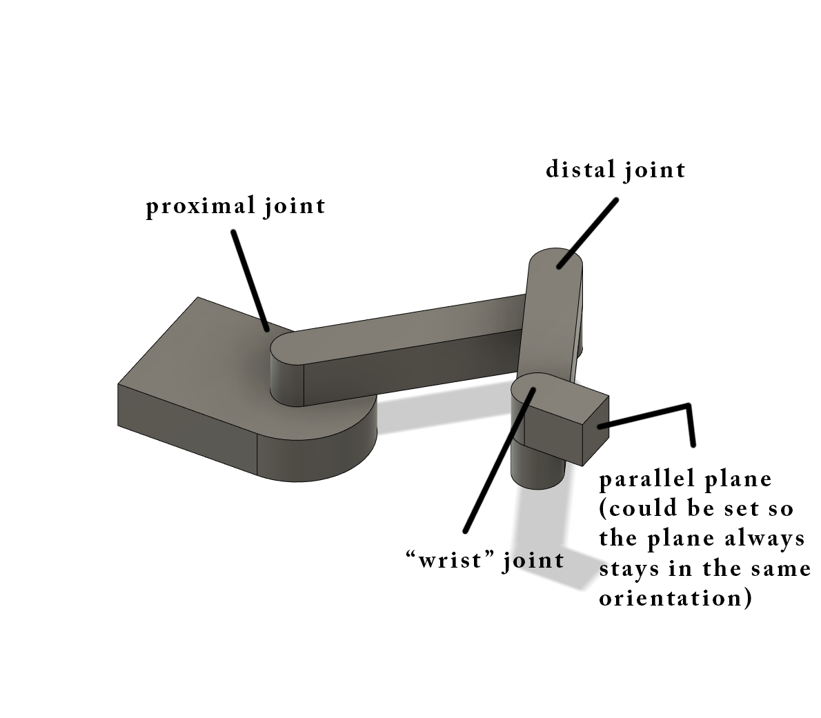
What I mean by having a stationary plane is that there is a face (which you would attach your tool to) that always stays in the same orientation. The plane/face could be set to always be perpendicular/parallel to the x/y axis with an offset if you wanted to.I hope that helps.
-
Thanks, now I understand. The kinematics could be implemented as a variation of the existing Scara kinematics by adding two things:
- Calculating the movement required of the third joint, which is just the negation of the sum of the angles of the other two joints, multiplied by the steps/degree of that motor;
- Adding the XY offset of the tool from the wrist joint to the position of the proximal joint to get the effective position of the proximal joint.
You would need to add a new kinematics class, or add a feature to the existing SCARA kinematics class; but it doesn't look difficult to me.
-
@dc42 said in 3rd rotation axis for SCARA kinematics:
negation of the sum
This is what I have been able to figure out so far. I'm not terribly good at coding so this is the way that I went about thinking about it.
//debugPrintf("psi = %.2f, theta = %.2f\n", psi * RadiansToDegrees, theta * RadiansToDegrees);

	motorPos[X_AXIS] = lrintf(theta * stepsPerMm[X_AXIS]);
	motorPos[Y_AXIS] = lrintf((psi - (crosstalk[0] * theta)) * stepsPerMm[Y_AXIS]);
	motorPos[Z_AXIS] = lrintf((machinePos[Z_AXIS] - (crosstalk[1] * theta) - (crosstalk[2] * psi)) * stepsPerMm[Z_AXIS]);
	motorPos[E1_AXIS] = lrintf(-1 * (theta + psi) * stepsPerMm[E1_AXIS])
It is supposed to change the motor position as you stated using the 5th stepper driver, E1 (I think, unless I have to define a new axis rather than just using E1) to where there would be the face in one orientation. Do you think this works/is there a better way of defining/coding this?
-
Yes you need to create a new axis (for example, U) using the M584 command:
M584 X0 Y1 Z2 E3 U4 P3
The P3 parameter hides the new axis. Specify the steps/mm and motor currents for the U axis in the M92 and M906 commands as usual. Then in your added line of code use [3] instead of [E1_AXIS].
-
I've been working on a scara arm for some time, I'm glad to try the 3rd axis but I don't know how to recompile the firmware to reload on a duet is there a guide? or if it is not so complicated can you explain how to do it? thanks!