Using U-axis/driver[3] in custom kinematics
-
@koaldesigns
Hi! I built a scara like yours, I've been following you since you made this post

it would be very useful! be able to use a 4 axis that holds position on the distal end, as you are trying to do! were you able to get your modified firmware to work? -
@tony73 No, I haven't gotten the firmware to work properly yet. I'm not skilled enough at coding to know how to do it properly, but I have tried. I am hoping that dc42 will be able to look at it at some point if he gets the time.
-
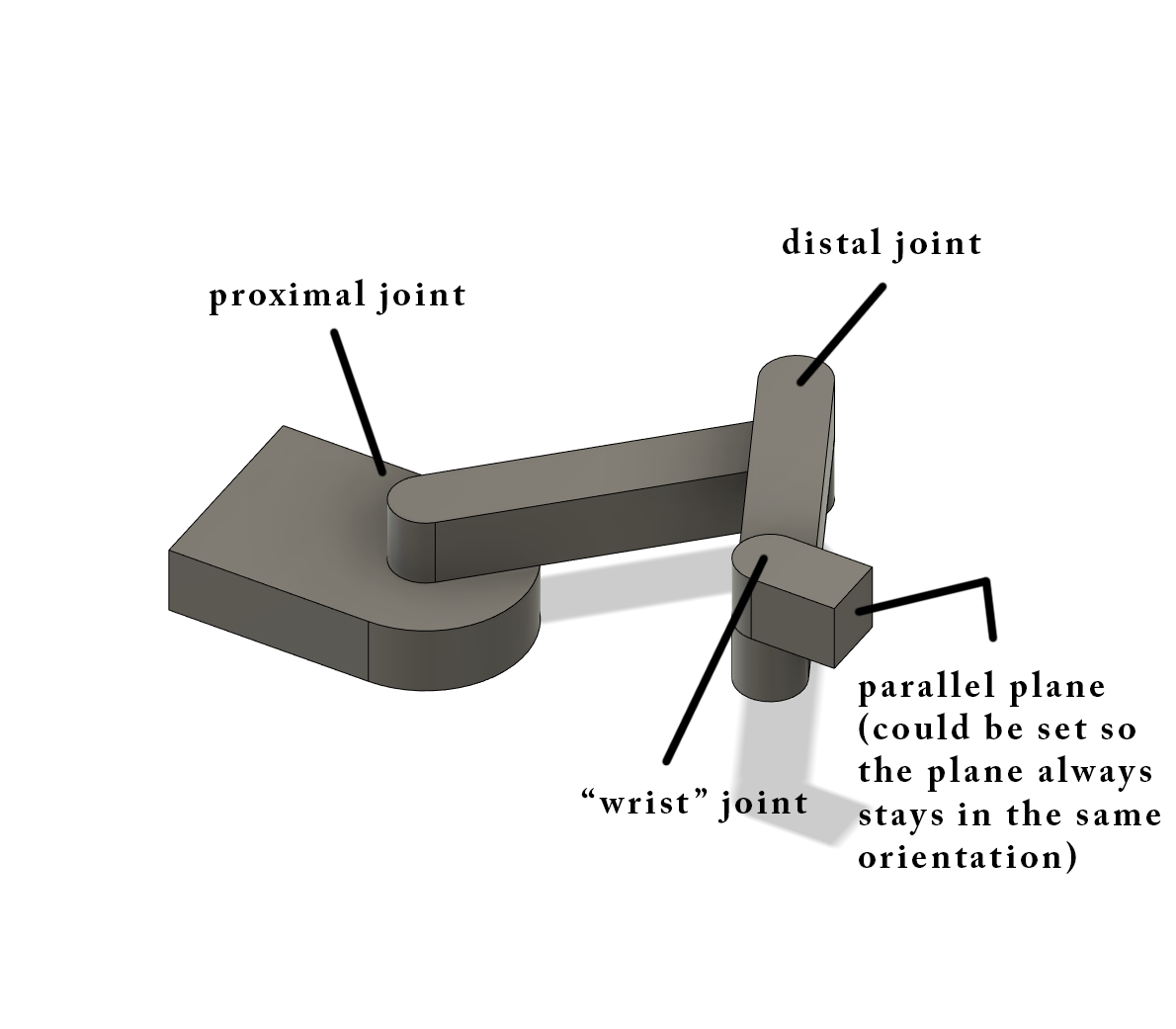
I have been developing and building a 4-axis (I think) SCARA arm/3D printer. It has a linear ball-screw driven Z-axis, and 3 joints (proximal, distal, and wrist).
This is the entire machine minus the wrist joint:

This is the wrist joint:

This wrist joint would add the ability to either have the tool always be pointed in the same direction or allow the wrist angle to be set using a 3rd rotational axis which could either use a U axis or a W axis and would allow for a 45 degree hotend and the ability to use the ZHAW slicer and printing using a 45 degree rotating hotend.
This is a concept of having the tool be able to stay in the same orientation/position:
Currently, the wrist joint uses a NEMA11 motor which is mounted to the joint/distal arm to control the position of the joint.
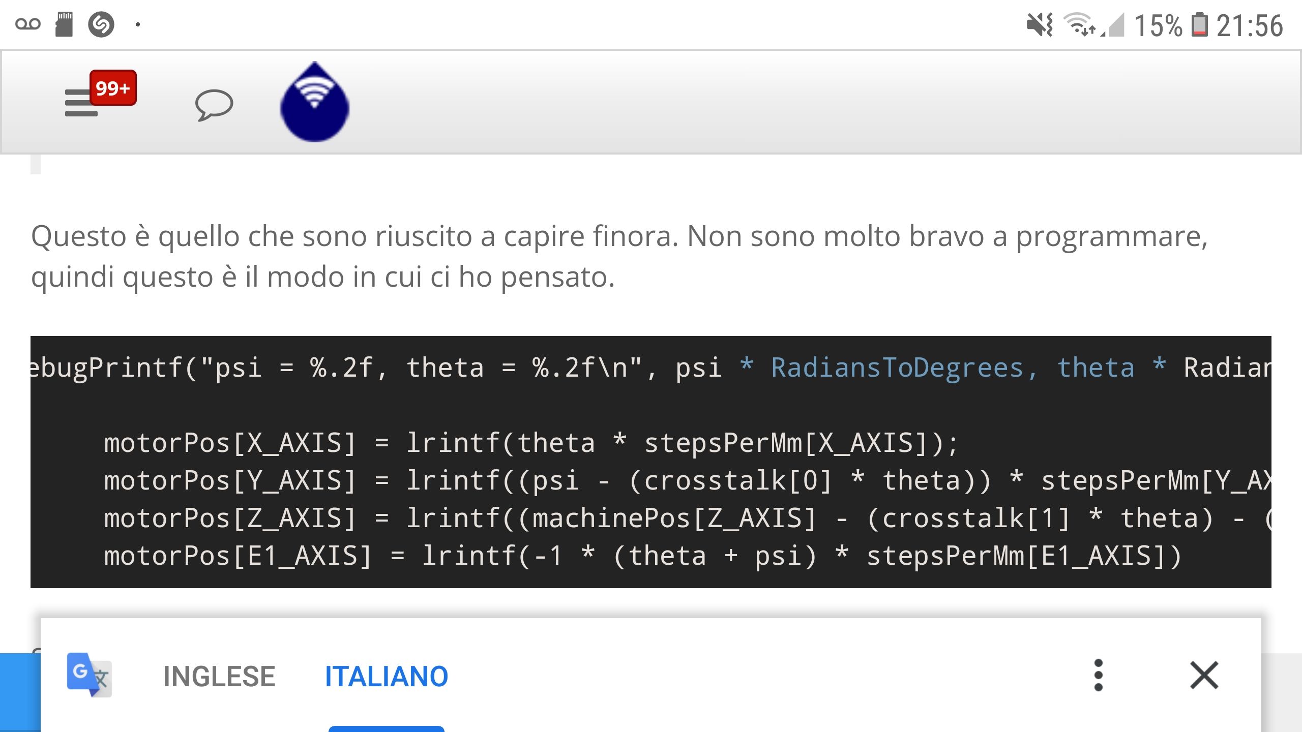
The problem is that I am terrible at coding and modifying the kinematic systems that are already in place. My current change has it so that the wrist joint will always stay in the same position and modifies the SCARA kinematics class which keeps the joint in the same orientation:
//debugPrintf("psi = %.2f, theta = %.2f\n", psi * RadiansToDegrees, theta * RadiansToDegrees); motorPos[X_AXIS] = lrintf(theta * stepsPerMm[X_AXIS]); motorPos[Y_AXIS] = lrintf((psi - (crosstalk[0] * theta)) * stepsPerMm[Y_AXIS]); motorPos[Z_AXIS] = lrintf((machinePos[Z_AXIS] - (crosstalk[1] * theta) - (crosstalk[2] * psi)) * stepsPerMm[Z_AXIS]); motorPos[3] = lrintf(-1 * (theta + psi) * stepsPerMm[3]) This works for now, but it does not allow angular control of the wrist to my knowledge.
My idea would be to add some other definition to the SCARA kinematics class (I was thinking "W" for wrist) which would allow for the rotation of the wrist joint. A gcode signal in the M669 command which would include "W0" meaning that the wrist joint would hold its orientation in relation to the x-axis, and the "W1" command which would allow for a gcode defined rotational position in relation to the x-axis using the U or W command like a G1 X50 Y50 Z50 U/W90 which would have the tool 90degrees clockwise to the x-axis I believe. A "W3" command could even be used so the tool stays static and has no movement, so it is always in line with the distal arm. Any of the "W" commands could be changed to make more sense this is just my idea.
From my terrible understanding of code it would be something like:
motorPos[3] = lrintf(((-1 * (theta + psi)) + U-Angle Position) * stepsPerMm[3])Which would keep the tool in the same orientation and then add or subtract the rotational position value.
I don't know how to implement the configuration of the "W" command using code but that is my best attempt at it. How would I/someone go about trying to configure or even make a new kinematics class for this? Help would be appreciated.
-
Based off of this post, I have attempted to edit/add a new kinematics class called 4axisScaraKinematics which is similar to the regular SCARA kinematics but adds a wrist joint.
As of now (I think), the wrist joint is defined by the "E" parameter and the "W" parameter in the M669 command. The "E" parameter specifies the maximum and minimum beta (or wrist) angles which are only use for homing (I think). The "W" command should change the wrist type which is present. W=0 or no W, wrist is in the same orientation as the distal arm: W=1, the wrist has a definable orientation in relation to the x-axis using motor[3]: W=2, the wrist will keep the same orientation as the x-axis. This is done by using multiple an if/if else/else statement to change the calculation depending on what value "W" is.
The main things I am worried about currently are that the kinematics class is not defined anywhere else because I don't know how I would go about doing that.
I have very limited coding experience, so I do no know if it will work or even compile as of yet. I was hoping to receive feedback on what could be changed or if it would even work in the first place.
Here is where you can find the RRF fork, specifically the kinematics class 4axisScaraKinematics.ccp.
-
Most of the kinematics classes, including SCARA AFAIR, allow you to add additional axes that move independently of the usual axes. So it is likely possible to drive a wrist joint by using the standard SCARA kinematics and creating an extra W axis. Have you tried that?
-
@dc42 Yes, I have tried making an extra W axis, not in the SCARA kinematic itself but using the the gcode commands to create a W axis. The problem I am having is that I need the W axis to move in relation to the proximal and distal arms which I am having trouble figuring out. The needed kinematics would be something like:
((-1 * (theta + psi) + wAngle[W_AXIS]) * stepsPerMm) Unless I am not understanding what you are trying to say.
-
I agree, you do need modified kinematics.
Your best bet may be to modify the existing SCARA kinematics class, preferably using #if blocks ot isolate the new code. Alternatively, if you can get your new class to compile, then you can add it as an additional kinematics.
-
@dc42 I manged to modify the firmware and got it to compile... The problem is that the actual physical wrist joint doesn't move when it should. Like the code is in there and it compiles, but the code doesn't seem to physically move the joint.
-
Have you added a new M669 type number, and used it to select your new kinematics?
-
Which branch of your fork did you add the new class to? The link to the .cpp file is broken.
-
I see, you added your changes to ScaraKinematics.cpp in the 3.02 branch.
-
I used the 3.02 dev, this is the more advanced change, the smaller change is saved locally somewhere. Right now its just a modification of the scarakinematics.cpp and .h files.
-
The code compiles and can be flashed onto the duet, the main arm functions work, but the wrist joint doesn't move in relation. It could be possible that the links/calls (?) between the .cpp and .h file are broken or I have the math in the wrong place.
-
You've added variable 'beta' but I can't see any code that sets its value.
-
The variable beta is supposed to be the offset of the wrist joint angle in relation to the x-axis. What should it be defined as? Also, I believe that the wrist joint should still stay in the same orientation to the x-axis even if beta isn't defined unless I'm understanding the code wrong.
-
I have added you to the repo editors so you can change whatever you feel would be incorrect.
-
I suggest you get rid of 'float beta' in the .h file because it doesn't need to be stored.
In line 167 of the .cpp file replace 'beta' by 'machinePos[3]'.
In line 194 replace 'beta' by '((float)motorPos[3]/stepsPerMm[3])'.
That doesn't handle enforcing wrist angle limits, but may get movement working.
-
Okay, I will add those changes, see what happens, and report back the results. Thank you
-
@dc42 I have flashed the firmware to the machine. It compiled with no errors as expected, but the wrist joint still does not operate. I can independently move the wrist joint just using G1 H2 commands on the U-Axis (what I have the wrist defined as currently).
Here is my current M669 if that could be the problem: M669 K4 P376 D376 A-137:110 B0:172 C-1:0:0 X0 Y0 W2 E-180:180
I am going to play with the kinematics some more and see if I can get it to work.
-
I tried a simplified movements kinematics for the wrist joint which no longer has the wrist modes. It also does not work. I have no idea why the wrist joint doesn't move when the proximal and distal joints do.
Here is the simplified kinematics which should only keep the wrist in line with the x-axis (it doesn't actually do this).
motorPos[3] = lrintf((-1 * (theta + psi)) * stepsPerMm[3]);This is my current config.g if there is anything wrong in that:
M669 K4 P376 D376 A-137:110 B0:172 C-1:0:0 X0 Y0 W2 E-180:180 ; Printer class SCARA, proximal/distal length, proximal min/max angle in relation to x-axis, distal min/max angle in relation to proximal arm, crosstalk factor (depends on mechanical setup) M584 X0 Y1 Z2 W3 E4 M208 X-752:752 Y-752:752 Z0:1270 W-360:360 ; Set min/max positions for each axis M201 X400 Y400 Z200 E800 ; Accelerations (mm/s^2) M203 X6000 Y6000 Z400 E4000 ; Maximum speeds (mm/min) M566 X300 Y300 Z20 E800 ; Maximum instant speed changes mm/minute ;Motor Settings M569 P0 S1 ; Drive 0 goes forwards M569 P1 S0 ; Drive 1 goes backwards M569 P2 S1 ; Drive 2 goes forwards M569 P3 S0 ; Drive 3 goes backwards M569 P4 S1 ; Drive 4 goes forwards M350 X16 Y16 Z16 E16:16 W16 I1 ; Set 16x microstepping with interpolation M92 X262.2222 Y262.2222 Z800 W65.55555 ; Set axis steps/degree, steps/mm M906 X1000 Y1000 Z1000 E800 W500 I60 ; Set motor currents (mA) and increase idle current to 60% ;Endstops M574 X1 S1 P"!xstop" ; X min active low endstop switch M574 Y1 S1 P"!ystop" ; Y min active low endstop switch ;M574 Z2 S1 P"zstop" ; Z max active high endstop switch ;M574 U2 S1 P"e0stop" ; U max active high endstop switch