3.3b-3 bug -pin mapping to expansion boards in config.g
-
Duet recognizes mapping of fans to out0 and out1 on X1D however only one pin is functional when manually entering in an M106 command. The other pin will not toggle voltage. I figured out a temporary work around - It appears to work if I manually enter the M950 and M106 command into the console. Once done, both pins work fine thereafter.
I've tried everything I could think of in terms of debugging on my own. I ensured all boards were running 3.3b-3, copy and pasted the M950 and M106 commands from a text file to ensure syntax was identical in config.g and when entering in manually after startup. I verified that the pin that doesn't toggle after startup does actually change by ~50milivolts when toggling off/on but voltage won't exceed a few hundred millivolts unless I re-enter the M950 and M106 commands manually.
The last thing I tries was putting a "G4 S1;" in-between each line within config.g that references an expansion board. Still no dice.
I've included diagnostics for D3MB6HC, X1D expansion and my config.g file below for review:
4/29/2021, 9:35:15 PM M122 B41
Diagnostics for board 41:
Duet EXP1XD firmware version 3.3beta3 (2021-04-21 20:34:11)
Bootloader ID: SAMC21 bootloader version 2.0 (2020-10-15b1)
Never used RAM 5668, free system stack 0 words
Tasks: Move(notifyWait,0.0%,153) HEAT(delaying,0.0%,75) CanAsync(notifyWait,0.0%,67) CanRecv(notifyWait,0.0%,78) CanClock(notifyWait,0.0%,67) MAIN(running,96.5%,415) AIN(delaying,3.5%,62), total 100.0%
Last reset 00:26:25 ago, cause: software
Last software reset data not available
Driver 0: position 0, 80.0 steps/mm, steps req 0 done 0
Moves scheduled 0, completed 0, in progress 0, hiccups 0, step errors 0, maxPrep 0, maxOverdue 0, maxInc 0, mcErrs 0, gcmErrs 0
Peak sync jitter 10, peak Rx sync delay 203, resyncs 2, no step interrupt scheduled
VIN: 12.7V
MCU temperature: min 23.1C, current 23.5C, max 23.7C
Ticks since heat task active 230, ADC conversions started 792986, completed 792986, timed out 0, errs 0
Last sensors broadcast 0x00000000 found 0 235 ticks ago, loop time 0
CAN messages queued 3740, send timeouts 0, received 8336, lost 0, free buffers 36, min 36, error reg 0
dup 0, oos 0, bm 0, wbm 0
4/29/2021, 9:35:12 PM M122
=== Diagnostics ===
RepRapFirmware for Duet 3 MB6HC version 3.3beta3 (2021-04-22 16:28:03) running on Duet 3 MB6HC v0.6 or 1.0 (SBC mode)
Board ID: 08DJM-956L2-G43S8-6J1DD-3S86K-TB36F
Used output buffers: 1 of 40 (15 max)
=== RTOS ===
Static ram: 149960
Dynamic ram: 63692 of which 0 recycled
Never used RAM 140540, free system stack 200 words
Tasks: SENSORS(delaying,0.0%,30) Linux(ready,6.2%,22) HEAT(delaying,0.0%,275) Move(notifyWait,0.0%,150) CanReceiv(notifyWait,0.0%,798) CanSender(notifyWait,0.0%,373) CanClock(delaying,0.0%,353) TMC(notifyWait,7.2%,93) MAIN(running,86.4%,1260) IDLE(ready,0.2%,19), total 100.0%
Owned mutexes: HTTP(MAIN)
=== Platform ===
Last reset 00:01:43 ago, cause: software
Last software reset at 2021-04-29 21:33, reason: User, none spinning, available RAM 140540, slot 2
Software reset code 0x0012 HFSR 0x00000000 CFSR 0x00000000 ICSR 0x0044a000 BFAR 0x00000000 SP 0x00000000 Task Linu Freestk 0 n/a
Error status: 0x00
Aux0 errors 0,0,0
Aux1 errors 0,0,0
Step timer max interval 127
MCU temperature: min 26.8, current 27.1, max 27.3
Supply voltage: min 12.7, current 12.8, max 12.8, under voltage events: 0, over voltage events: 0, power good: yes
12V rail voltage: min 11.9, current 12.0, max 12.1, under voltage events: 0
Heap OK, handles allocated/used 0/0, heap memory allocated/used/recyclable 0/0/0, gc cycles 0
Driver 0: position 0, standstill, reads 56635, writes 14 timeouts 0, SG min/max 0/0
Driver 1: position 0, standstill, reads 56636, writes 14 timeouts 0, SG min/max 0/0
Driver 2: position 0, standstill, reads 56639, writes 11 timeouts 0, SG min/max 0/0
Driver 3: position 0, standstill, reads 56636, writes 14 timeouts 0, SG min/max 0/0
Driver 4: position 0, standstill, reads 56636, writes 14 timeouts 0, SG min/max 0/0
Driver 5: position 0, standstill, reads 56636, writes 14 timeouts 0, SG min/max 0/0
Date/time: 2021-04-29 21:35:11
Slowest loop: 0.57ms; fastest: 0.04ms
=== Storage ===
Free file entries: 10
SD card 0 not detected, interface speed: 37.5MBytes/sec
SD card longest read time 0.0ms, write time 0.0ms, max retries 0
=== Move ===
DMs created 125, maxWait 0ms, bed compensation in use: none, comp offset 0.000
=== MainDDARing ===
Scheduled moves 0, completed moves 0, hiccups 0, stepErrors 0, LaErrors 0, Underruns [0, 0, 0], CDDA state -1
=== AuxDDARing ===
Scheduled moves 0, completed moves 0, hiccups 0, stepErrors 0, LaErrors 0, Underruns [0, 0, 0], CDDA state -1
=== Heat ===
Bed heaters = 0 -1 -1 -1 -1 -1 -1 -1 -1 -1 -1 -1, chamberHeaters = -1 -1 -1 -1
Heater 2 is on, I-accum = 0.0
=== GCodes ===
Segments left: 0
Movement lock held by null
HTTP* is doing "M122" in state(s) 0
Telnet is idle in state(s) 0
File is idle in state(s) 0
USB is idle in state(s) 0
Aux is idle in state(s) 0
Trigger* is idle in state(s) 0
Queue is idle in state(s) 0
LCD is idle in state(s) 0
SBC is idle in state(s) 0
Daemon is idle in state(s) 0 0, running macro
Aux2 is idle in state(s) 0
Autopause is idle in state(s) 0
Code queue is empty.
=== CAN ===
Messages queued 920, send timeouts 0, received 846, lost 0, longest wait 1ms for reply type 6018, peak Tx sync delay 5, free buffers 49 (min 48)
=== SBC interface ===
State: 0, failed transfers: 0
Last transfer: 1ms ago
RX/TX seq numbers: 3659/3660
SPI underruns 0, overruns 0
Number of disconnects: 0, IAP RAM available 0x2cf4c
Buffer RX/TX: 0/0-0
=== Duet Control Server ===
Duet Control Server v3.3-b3
Code buffer space: 4096
Configured SPI speed: 8000000 Hz
Full transfers per second: 36.01
Codes per second: 1.03
Maximum length of RX/TX data transfers: 3692/1188;Config.g
; General preferences
G90 ; send absolute coordinates...
M83 ; ...but relative extruder moves
M550 P"TestPrinter" ; set printer name
; Drives
M569 P0.3 S0 ; physical drive 0.3 goes forwards
M569 P0.2 S1 ; physical drive 0.2 goes forwards
M569 P0.0 S1 ; physical drive 0.0 goes forwards
M569 P0.1 S1 ; physical drive 0.0 goes forwards
M569 P0.4 S1 ; physical drive 0.4 goes forwards
M569 P0.5 S1 ; physical drive 0.5 goes forwards
M569 P40.0 S0 R0 T5:5:5:5 ; change enable polarity, active = disable drive, pulse profile
G4 S1 ;Wait for expansion board to start
M569 P41.0 S1 R0 T20:20:20:20 ; change enable polarity, active = disable drive, pulse profile
G4 S1 ; Wait for expansion board to start
M584 X0.3 Y40.0 Z0.0:0.1 E0.4:0.5 ; set drive mapping
M350 X8 Z16 E16:16 I1 ; configure microstepping with interpolation
M92 X160.00 Y640.00 Z3316.00 E102.00:141.00 ; set steps per mm
M566 X1000.00 Y1000.00 Z60.00 E150.00:150.00 ; set maximum instantaneous speed changes (mm/min)
M203 X4500.00 Y4500.00 Z180.00 E3600.00:3600.00 ; set maximum speeds (mm/min)
M201 X3000.00 Y3000.00 Z20.00 E250.00:250.00 ; set accelerations (mm/s^2).
M906 X2000 Z1300 E1800:1800 I30 ; set motor currents (mA) and motor idle factor in per cent
M84 S30 ; Set idle timeout
M572 D0 S0.55 ;Set pressure advance for drive 0
M572 D1 S0.55 ;Set pressure advance for drive 1; Axis Limits
M208 X0 Y0 Z0 S1 ; set axis minima
M208 X360 Y240 Z200 S0 ; set axis maxima; Endstops
M574 X1 S1 P"!io1.in" ; configure active-high endstop for high end on X via pin io1.in
M574 Y2 S1 P"!io2.in" ; configure active-high endstop for high end on Y via pin io2.in
M574 Z1 S2 ; configure Z-probe endstop for low end on Z; Z-Probe
M558 P1 C"io4.in" H5 F120 T6000 ; set Z probe type to unmodulated and the dive height + speeds
G31 P500 X0 Y0 Z0.85 ; set Z probe trigger value, offset and trigger height
M557 X40:260 Y90:240 S220:150 ; define mesh grid; Heaters
M308 S0 P"temp0" Y"thermistor" T100000 B3950 ; configure sensor 0 as thermistor on pin temp0
M950 H0 C"out0" T0 ; create bed heater output on out0 and map it to sensor 0
M307 H0 R0.793 C768.4 D2.16 S1.00 V30.9 ; disable bang-bang mode for heater and set PWM limit
M140 H0 ; map heated bed to heater 0
M143 H0 S170 ; set temperature limit for heater 0 to 170C
M308 S1 P"temp1" Y"pt1000" R2200 ; configure sensor 1 as PT1000 on pin temp1
M950 H1 C"out1" T1 ; create nozzle heater output on out1 and map it to sensor 1
M307 H1 R2.716 C278.8 D5.98 S1.00 V11.8 ; disable bang-bang mode for heater 1 and set PWM limit
M143 H1 S410 ; set temperature limit for heater 1 to really hot
M308 S2 P"temp2" Y"pt1000" R2200 ; configure sensor 2 as PT1000 on pin temp2
M950 H2 C"out2" T2 ; create nozzle heater output on out2 and map it to sensor 2
M307 H2 R2.648 C312.5 D6.77 S1.00 V11.8 B0 ; disable bang-bang mode for heater 2 and set PWM limit
M143 H2 S410 ; set temperature limit for heater 2 to really hot;tools
M308 S10 P"0.spi.cs1" Y"dht22" A"Chamber Temp" ; configure sensor 10 as DHT22 temperature sensor on pin spi.cs1
M308 S11 P"S10.1" Y"dhthumidity" A"Chamber Hum[%]" ; configure sensor 11 as DHT22 humidity sensor on second output of pin spi.cs1
M308 S12 P"io6.out" Y"dht22" A"Material Temp" ; configure sensor 12 as DHT22 temperature sensor on pin io6.out
M308 S13 P"S12.1" Y"dhthumidity" A"Material Hum[%]" ; configure sensor 13 as DHT22 humidity sensor on second output of pin io6.out
M950 H3 C"out3" T10 ; create chamber heater output on out3 and map it to sensor "10"
M950 H4 C"out4" T11 ; create chamber heater output on out4 and map it to sensor "11"
M950 H5 C"out5" T12 ; create chamber heater output on out5 and map it to sensor "12"
M950 H6 C"out6" T13 ; create chamber heater output on out6 and map it to sensor "13"
; Fans
M950 F0 C"out7" Q500 ; create fan 0 on pin out7 and set its frequency
M106 P0 S0 H-1 ; set fan 0 value. Thermostatic control is turned off
M950 F1 C"out8" Q500 ; create fan 1 on pin out8 and set its frequency
M106 P1 S0 H-1 ; set fan 1 value. Thermostatic control is turned off
;Remap pins to do fun stuff
M950 F6 C"41.out0" Q500 ; create a GPIO pin number 6 on 1XD board at CAN address 41 for the fan pwm output.
G4 S1 ; Wait a second
M106 P6 S0 H-1 ; Set fan 6 value. Thermostatic control is turned off.
G4 S1 ; Wait another second
M950 F7 C"40.out1" Q500 ; create a GPIO pin number 7 on 1XD board at CAN address 41 for the fan pwm output.
G4 S1 ; Wait another second
M106 P7 S0 H-1 ; Set fan 7 value. Thermostatic control is turend off.
G4 S1 ; Wait just one more second to pray that the printign gods allow this to work")
; Tools
M563 P1 S"Support" D1 H2 ; define tool 1
G10 P1 X20 Y0 Z0 ; set tool 1 axis offsets
G10 P1 R0 S0 ; set initial tool 1 active and standby temperatures to 0C
M563 P2 S"Model" D0 H1 ; define tool 2
G10 P2 X0 Y0 Z0 ; set tool 2 axis offsets
G10 P2 R0 S0 ; set initial tool 2 active and standby temperatures to 0C
M563 P3 S"temps and hums" D1 H3:4:5:6 ; define virtual tool 3
G10 P3 X0 Y0 Z0 ; set tool 3 axis offsets
G10 P3 R0 S0 ; set initial tool 3 active and standby temperatures to 0C; Miscellaneous
M575 P1 S1 B57600 ; enable support for PanelDue
M501 ; load saved parameters from non-volatile memory
M911 S10 R11 P"M913 X0 Y0 G91 M83 G1 Z3 E-5 F1000" ; set voltage thresholds and actions to run on power loss
T1 ; select first tool -
@print3d said in 3.3b-3 bug -pin mapping to expansion boards in config.g:
M569 P40.0 S0 R0 T5:5:5:5 ; change enable polarity, active = disable drive, pulse profile
G4 S1 ;Wait for expansion board to start
M569 P41.0 S1 R0 T20:20:20:20 ; change enable polarity, active = disable drive, pulse profile
G4 S1 ; Wait for expansion board to start
...
Remap pins to do fun stuff
M950 F6 C"41.out0" Q500 ; create a GPIO pin number 6 on 1XD board at CAN address 41 for the fan pwm output.
G4 S1 ; Wait a secondYou need the one second delay before you first refer to anything on any expansion board.
You only need a single one-second delay in config.g. Its purpose is to make sure that the expansion board has started up and is ready to receive CAN data, because expansion boards may take longer to start up than the main board.
Duet WiFi hardware designer and firmware engineer
Please do not ask me for Duet support via PM or email, use the forum
http://www.escher3d.com, https://miscsolutions.wordpress.com -
@dc42 I made this change to have a single one second delay at the first reference of an expansion board in config.g
This resolved the issue on 1XD board 41 but I'm still having strange errors on board 40 (other 1XD board) leading me to believe there is perhaps something else going on.
I'm using 40 to communicate with an external driver. It works perfect for this but will not recognize temp0, out0 or out1 (very weird)
I'm using board 41 now for the out0, out1, and temp0 pins, no driver and that works fine.
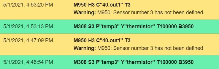
Trying to debug further, I put the B40 thermistor into MB6HC temp0, changed the config.g accordingly so board 40 is now only responsible for driving a motor and sending outputs through 40.out0, 40.out1. The error I'm receiving now is the sensor is not defined which is strange because it is defined and is outputting a temperature reading on DWC. I've included a photo of the console message I'm getting after manually inputting the definitions two separate times.
I should also note that when I set "heater 3 to zero it immediately faults without a delay from not increasing fast enough. My gut is there's some issue unknown to me around multi-board communications in SBC mode.
-
Update #2
I double checked firmware versions and noticed MB6HC was updated to 3.3rc-1 while 1XD boards were still running 3.3b3. After updating firmware on the 1XD boards, the heaters now "exist" again
however there remains two significant bugs, one minor bug I just can't figure out.#1 (major) - when using 41.Out0 and 41.Out1 to control external heater relays, the channel connected to Out0 immediately faults. This only happens when heaters in config.g are mapped to both 41.out0 and 41.out1, I've tried commenting out each separately to test individual functionality and this seems to work fine.
#2 (major) - for whatever reason I can't get any functionality on any pins on board 40 other than the step/dir/enable. 40.temp0, 40.out0 and 40.out1 simply aren't responding and the fuse remains intact so I'm scratching my head on what's going on here and will try to flash to factory and reimplement as 42 next.
#3(minor-ish) temo0 on board 41 is reading in thermistor values 3-4C above actual. When I unplug the thermistor, the value goes to -3.2 vs -273 as expected. I measured the resistance across the thermistor with a volt meter and it was normal, I then connected the thermistors to the main board and they read room temp. A quick unplug and plug back into board 41 again reads 4C above ambient. I can deal with 4c if its consistent across all set points and will run tests with a thermal camera to confirm its a constant difference vs changing at different setpoints.
Any help figuring out these would be greatly appreciated. As a final note, all of the Vin and grounds are tied to single points so there shouldn't be any ground loops in the wiring.
-
@print3d said in 3.3b-3 bug -pin mapping to expansion boards in config.g:
I made this change to have a single one second delay at the first reference of an expansion board in config.g
When you say "at the first reference", do you mean "before the first reference"? That's where it needs to be, before not after.
Re #3 the thermistor inputs are less accurate on the 1XD than on other boards because they are typically not used, or used only to monitor non-critical items such as stepper motor temperatures. However, you can calibrate them manually for better accuracy as described at https://duet3d.dozuki.com/Wiki/Calibrating_thermistor_and_PT1000_readings?revisionid=HEAD#Section_Manual_calibration.
Duet WiFi hardware designer and firmware engineer
Please do not ask me for Duet support via PM or email, use the forum
http://www.escher3d.com, https://miscsolutions.wordpress.com -
@dc42 yes I have “G4 S1;” in the line above the first reference to an external board. In this case it’s board 40, declaring its driving capability and pulse profile for later use in config.g.
I’m just perplexed as to why the issue of functionality the out0,1 pins aren’t consistent across both x1d boards while at the same time there is some functionality in each. (40 is driving y axis, 41 will eventually drive x axis but currently just used for temp0 and triggering SSR’s.
Thank you for the tip on calibration of temp0, I’ll proceed to tune this piece.