Plan to switch from normal steppers to 1HCL+ magnetic encoders
-
@dc42 Something to ask
When you do manual tuning with the plugin after it is finished.
How to save the tuned parameters?
Do I need to enter them in config.g in the 569.1 command? -
@martin7404 yes you need to put the new parameters in the M569.1 command in config.g.
Duet WiFi hardware designer and firmware engineer
Please do not ask me for Duet support via PM or email, use the forum
http://www.escher3d.com, https://miscsolutions.wordpress.com -
@dc42 does this manual tooling look OK?
This is what I cma up after following the tuning guide
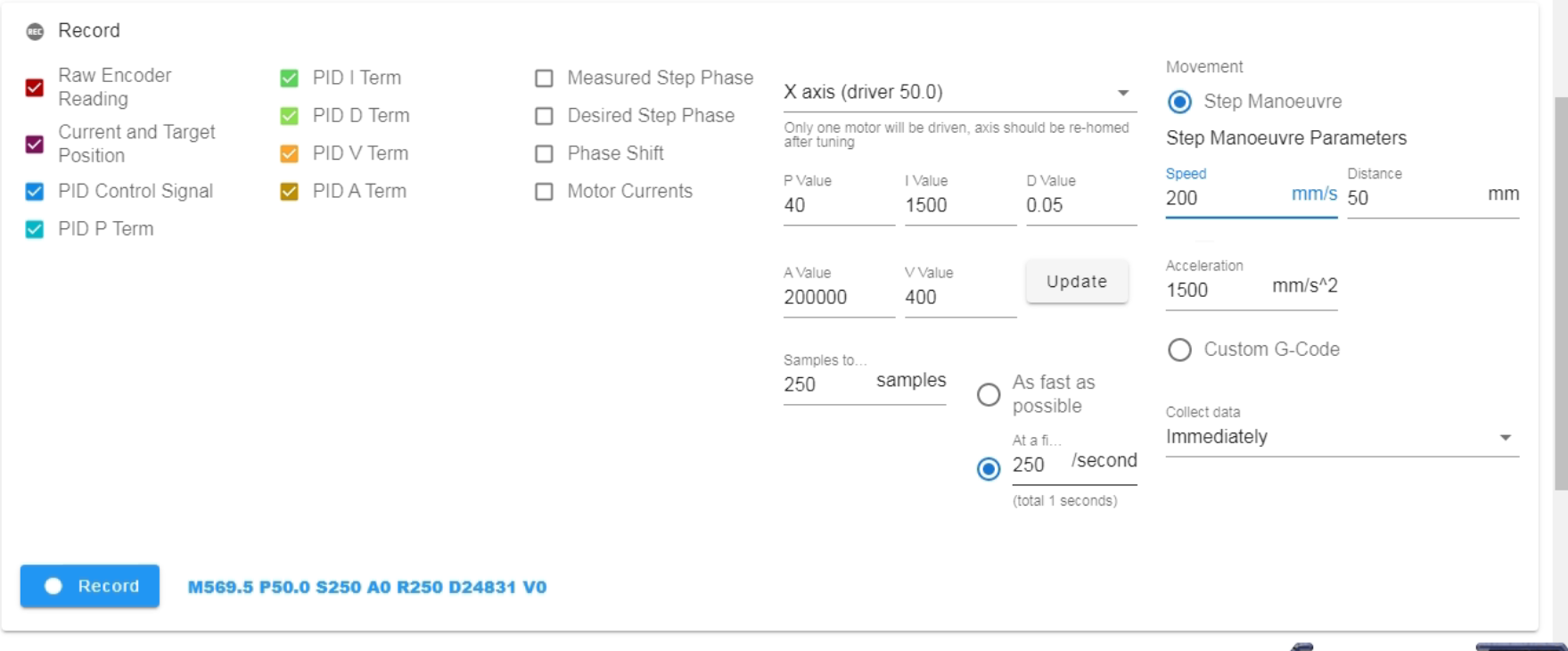
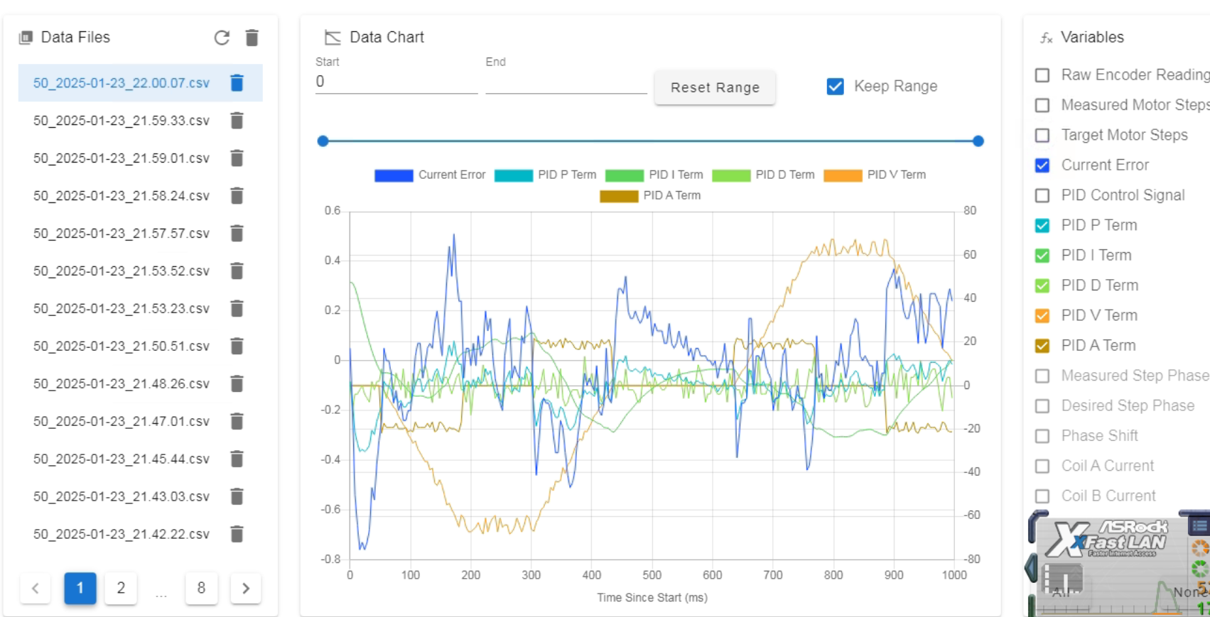
-
this is the second motor
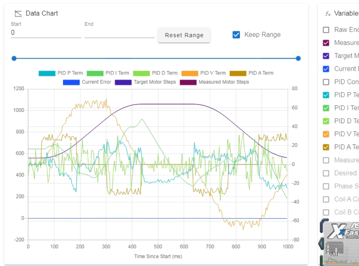
-
the final config.g
; Configuration file for Duet 3 (firmware version 3) ; executed by the firmware on start-up ; ; generated by RepRapFirmware Configuration Tool v3.2.3 on Thu May 27 2021 13:17:12 GMT+0300 (Eastern European Summer Time) ; General preferences G90 ; send absolute coordinates... M83 ; ...but relative extruder moves M550 P"CoreXY500" ; set printer name M669 K1 ; select CoreXY mode ; Network M552 P192.168.1.27 S1 ; enable network and acquire dynamic address via DHCP M586 P0 S1 ; enable HTTP M586 P1 S0 ; disable FTP M586 P2 S0 ; disable Telnet G4 S2 ;wait for expansion boards to start ; Drives M569.1 P50.0 T3 E4:8 S400 R40 I1500 D0.05 V400 A200000 H10 ; Configure the Duet 3 Expansion 1HCL board at CAN address 50 with a Duet 3 magnetic encoder, warn if 1 fullstep threshold exceeded, error if 2 full steps threshold exceeded. M569 P50.0 D4 S1 ; ;M569 P0.0 S1 ; physical drive 0.0 goes forwards ;M569 P0.1 S0 ; physical drive 0.1 goes forwards M569.1 P51.0 T3 E4:8 S400 R40 I1500 D0.05 V400 A200000 H10 ; Configure the Duet 3 Expansion 1HCL board at CAN address 50 with a Duet 3 magnetic encoder, warn if 1 fullstep threshold exceeded, error if 2 full steps threshold exceeded. M569 P51.0 D4 S0 M569 P0.3 S0 M569 P0.4 S1 M569 P0.5 S1 ; physical drive 0.2 goes forwards M569 P121.0 S1 ; physical drive 121.0 goes forwards M584 X50.0 Y51.0 Z0.3:0.4:0.5 E121.0 ; set drive mapping M350 X16 Y16 Z16 E16 I1 ; configure microstepping with interpolation M92 X160.00 Y160.00 Z8280.00 E395.70 ; set steps per mm ;M350 X32 Y32 Z16 E16 I1 M566 X300.00 Y300.00 Z50.00 E120.00 ; set maximum instantaneous speed changes (mm/min) M203 X12000.00 Y12000.00 Z150.00 E1200.00 ; set maximum speeds (mm/min) M201 X1000.00 Y1000.00 Z20.00 E500.00 ; set accelerations (mm/s^2) M906 Z1000 E800 I30 ; set motor currents (mA) and motor idle factor in per cent M906 X1700 Y1700 I30 M84 S30 ; Set idle timeout ; Axis Limits M208 X-26 Y0 Z0 S1 ; set axis minima M208 X500 Y330 Z365 S0 ; set axis maxima ; Endstops M574 X1 S4 ; configure sensorless endstop for low end on X M574 Y1 S4 ; configure sensorless endstop for low end on Y M574 Z1 S2 ; configure Z-probe endstop for low end on Z ;M574 E1 S1 ;Filament sensor BTT E1 M591 D0 P2 C"io8.in" S1 ;configure BTT smart filament sensor ; Z-Probe M671 X-31.39:250:531.36 Y-18:433.3:-18 S10 ; Locations left, center, right M558 P8 C"121.io2.in" H3 F1000 T6000 A20 S0.005 ; PINDA set Z probe type to switch and the dive height + speeds ;M308 S2 P"121.temp1" A"PINDA" Y"thermistor" T100000 B3950 ;M950 H2 C"out1" T2 ; create nozzle heater output on 121.out0 and map it to sensor 1 ;M307 H2 B0 S1.00 ; disable bang-bang mode for heater and set PWM limit ;M141 H2 ;M143 H2 S90 ; set temperature limit for heater 1 to 280C G31 P500 X30 Y0 Z1.48 ; set Z probe trigger value, offset and trigger height M557 X20:450 Y5:320 P5 ; define mesh grid ; Heaters M308 S0 P"temp0" Y"thermistor" T100000 B4138 ; configure sensor 0 as thermistor on pin temp0 M950 H0 C"out0" T0 Q10 ; create bed heater output on out0 and map it to sensor 0 M307 H0 B0 S1 ; disable bang-bang mode for the bed heater and set PWM limit M140 H0 ; map heated bed to heater 0 M143 H0 S130 ; set temperature limit for heater 0 to 120C M308 S1 P"121.temp0" Y"thermistor" T100000 B4725 C7.060000e-8 ; configure sensor 1 as thermistor on pin 121.temp0 M950 H1 C"121.out0" T1 ; create nozzle heater output on 121.out0 and map it to sensor 1 M307 H1 B0 S1.00 ; disable bang-bang mode for heater and set PWM limit M143 H1 S290 ; set temperature limit for heater 1 to 280C M308 S2 A"Chamber" P"temp2" Y"thermistor" T100000 B4725 C7.06e-8 M950 H2 C"out2" T2 ; create nozzle heater output on 121.out0 and map it to sensor 1 M307 H2 R0.001 A11 C99999 D4000 B1 ; disable bang-bang mode for heater and set PWM limit M141 H2 M143 H2 S70 ; Fans M950 F0 C"121.out1" ; create fan 0 on pin 121.out1 and set its frequency M106 P0 S0 B0.5 H-1 ; set fan 0 value. Thermostatic control is turned off M950 F1 C"121.out2" Q500 ; create fan 1 on pin 121.out2 and set its frequency M106 P1 S1 H1 T45 ; set fan 1 value. Thermostatic control is turned on ; Tools M563 P0 D0 H1 F0 ; define tool 0 G10 P0 X0 Y0 Z-0.15 ; set tool 0 axis offsets G10 P0 R0 S0 ; set initial tool 0 active and standby temperatures to 0C ; Custom settings are not defined M955 P121.0 I05 ;Accelerometer on Toolboard ; Miscellaneous M575 P1 S1 B57600 ; enable support for PanelDue M572 D0 S0.045 ; PA for ABS GD filament 0.4 nozzle M501 ; load saved parameters from non-volatile memory M911 S22.5 R23.5 P"M913 X0 Y0 G91 M83 G1 Z3 E-5 F1000" ; set voltage thresholds and actions to run on power loss ``' -
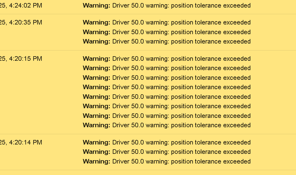
@dc42 Everything works but with 0.8 nozzle, I have to run pretty slow and there is too much vibration in closed-loop mode, so I switched to assisted open loop
I get a lot of these
Do you mean R value in M569.1 ?Muldex IDEX Duet2+Duex5
Custom CoreXY 600x400 Hemera , Duet3+Toolboard+1HCL closed loop
Sapphire Pro with Duet2, with closed-loop motors
custom high temp E3D tool changer with Duet2+Duex -
@martin7404 From time to time, it pauses due to these errors, and when I resume,e there is a slight layer shift
For now, for the big nozzle, I am switching to open loop with high current on the motors.
And will use a closed loop when printing with a smaller nozzle
May be in the future I will switch the motors to 1.8 and will test tuning them again -
@martin7404 the warning .messages mean that the M569.1 E value has been exceeded.
If the motors are noisy in closed loop mode, reduce the D term. If they tend to oscillate, reduce the R term or increase the D term.
Duet WiFi hardware designer and firmware engineer
Please do not ask me for Duet support via PM or email, use the forum
http://www.escher3d.com, https://miscsolutions.wordpress.com -
@dc42 In a closed loop, D is 0, and still, for a 0.8 nozzle, I tend to run at 30-40 mm/s, and at that speed, it is very noisy. The assisted open loop leads to shifts. Unfortunately, these parts are in production, and I just went back to open loop with reduced Acceleration and higher motor current. We will deal with the setup after this job is finished
-
@martin7404 After some time, printing with the machine, system started to mismatch the 3 Z motors during print
I thought one of my motors is going bad.
Still, after some testing, I found out that if I switch the A and B motors to the main board, completely eliminating the closed-loop boards, it works as before. So, for now, I am removing all HCL closed-loop electronics and writing off the time spent.
I will probably use the hardware in a future project. The machine is needed for production printing, and we remain the "Slow ABS printer" -
@martin7404 did you try reducing the M569.1 R term? If so, what was the result?
Duet WiFi hardware designer and firmware engineer
Please do not ask me for Duet support via PM or email, use the forum
http://www.escher3d.com, https://miscsolutions.wordpress.com -
@dc42, not good, the sensorless homing is not working onthe lower R setting. I believe the main problem is that I use 0.9 steppers, which do not allow me to properly tune the motors in closed loop
-
@martin7404 the M569.1 parameters only affect closed loop and assisted open loop modes, so they should have no effect when performing sensorless homing in open loop mode.
Getting 0.9deg motors working well in closed loop mode can be challenging. In particular, the encoder calibration is more critical and the maximum speed will be lower.