12V on the 5V rail
-
@Haggan90 said in 12V on the 5V rail:
@dc42 I connected 3.3V and nothing got hot.
When I connected USB I got 4.4V in the 3.3V rail...Remove the other blown chip too.
-
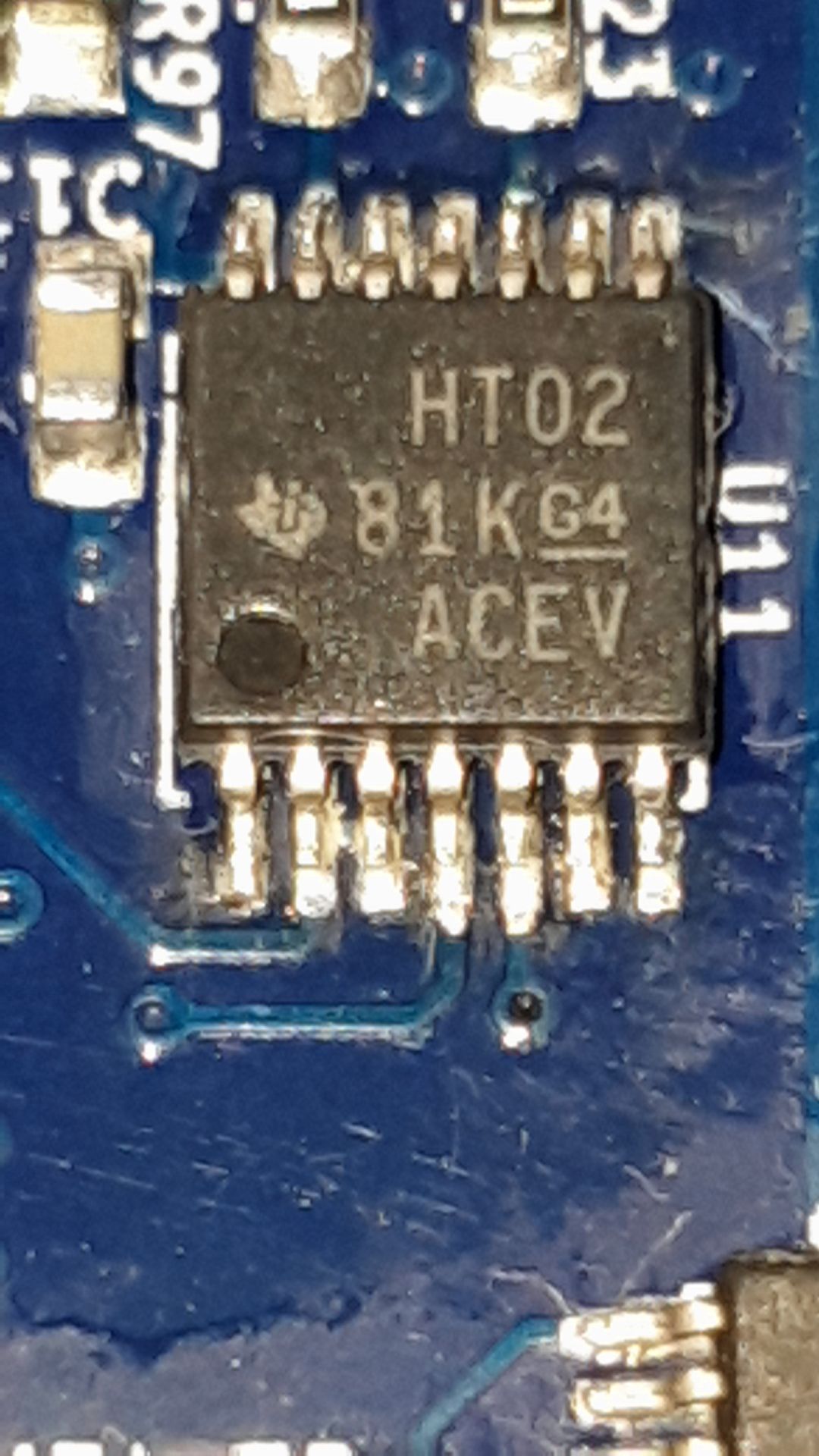
@dc42 You mean the U11 / 74HCT02?
-
-
@dc42 aha ok! I have to do that at work where we have a hot air solder gun
-
@dc42 Hi!
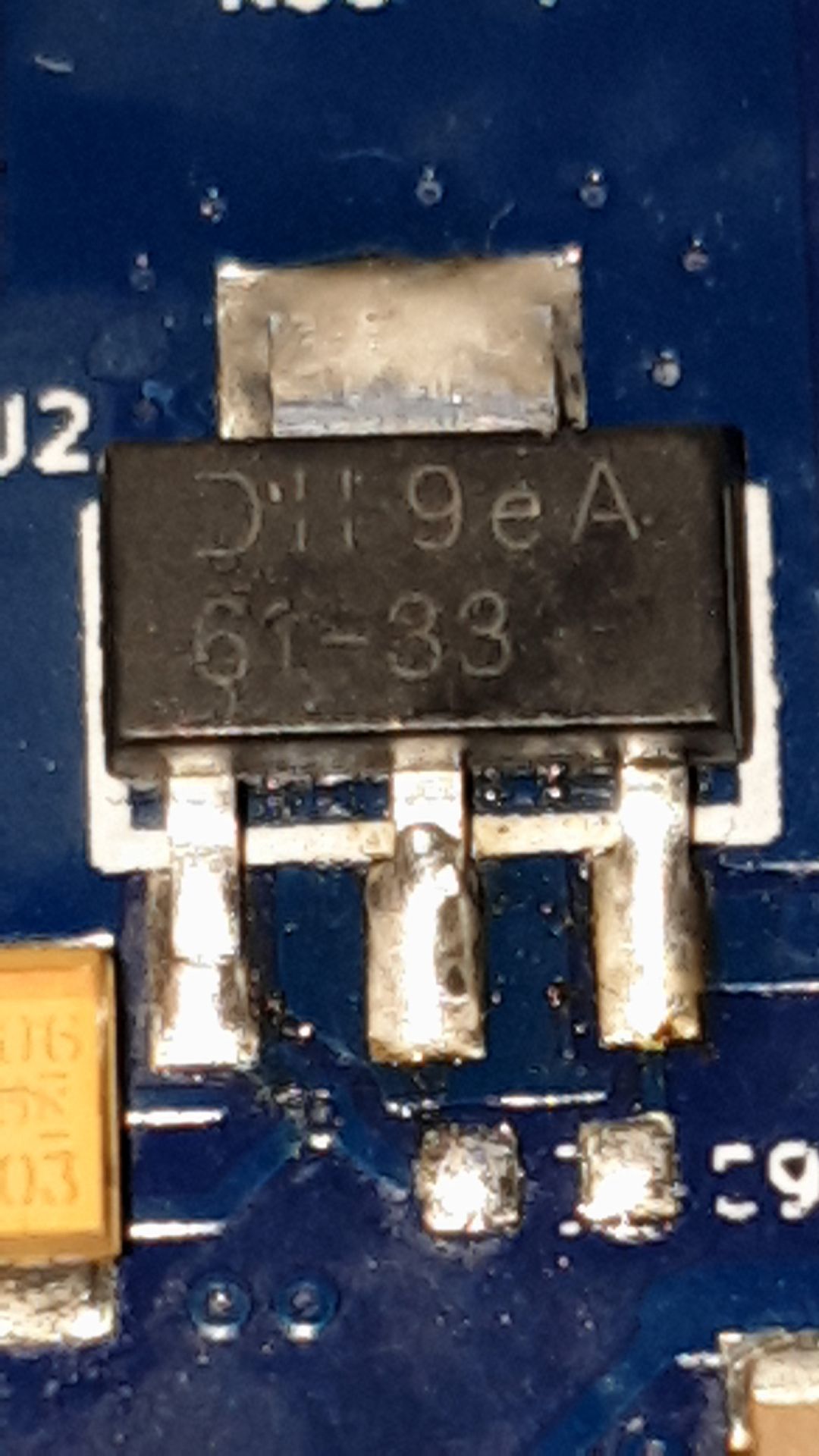
Sorry for taking such long time for this, but now I have manage to replace the U2 and U11.
When I connect the Duet to USB I get a warning of high current cunsumtion on the USB port, and U2 get's really hot.Do you have any slightest idea of what else could be broken?
-
What else is getting hot? Start by checking the processor, SD card (if it is in the socket), and WiFi module.
Are you certain that you used the correct chip to replace U2? Different hardware versions of the Duet WiFi use different chips in that position.
-
@dc42 hi!
As far as I can nothing else get's hit then the U2. Here are the new components.


-
What part number did you use for the 3.3V regulator, and what hardware revision Duet board is it? I think you may have used the wrong regulator.
-
@dc42 Hi,
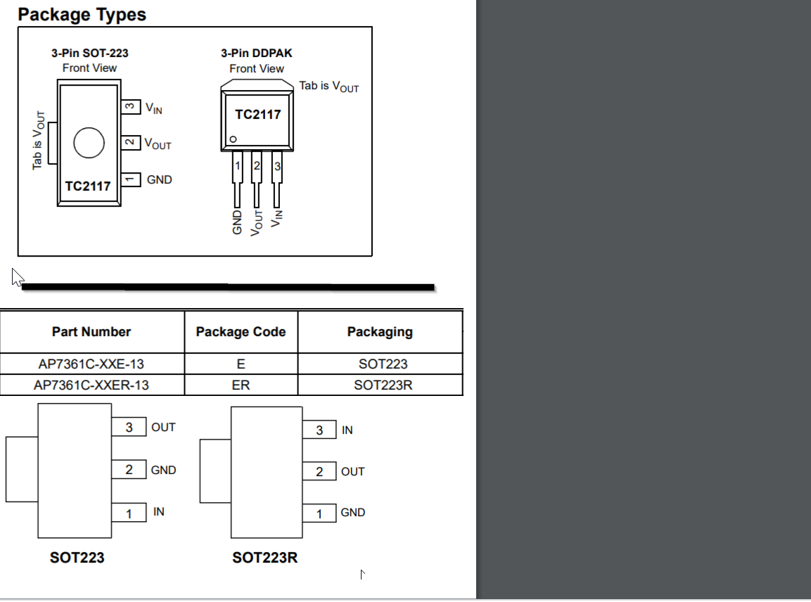
As voltage regulator I used a: AP7361C-33E-13
And as the U11 mosfet driver I used a : SN74HCT02PWR -
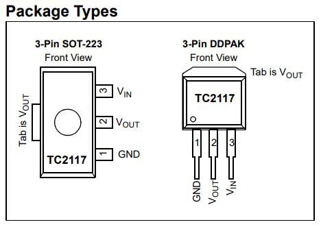
looks like the board is a revision 1.03 board that uses a TC2117 which is not compatible with AP7361C-33E-13 but
shouldcould be compatible with AP7361C-33ER-13
-
@bearer Aw crap haha

Might I have destroyed the PCB even more now? -
@Haggan90 not sure; i would guess u2 took the blunt of the force this time as well.
you'll just have to remove it and see if the board still works with external 3.3v I guess (or wait for the correct part)
But do double check it is a rev 1.03 board
-
@bearer Ok!
Yeah, It is a V1.03 board.
Is it possible that the Wifi Module and the SD card reader is OK or do I have to change one/both of them as well? -
@Haggan90 as I said I'm not sure, head isn't quite on the right way but I'm guessing you essentially fed -5v into the 3.3v output of the regulator which it didn't like.
odds are if nothing else got warm the damage is contained, but as i said, remove the wrong regulator and test it with an external supply and you'll have the answer.
-
@bearer said in 12V on the 5V rail:
but should be compatible with AP7361C-33ER-13
@Haggan90 just clicked in my head the AP7361C doesn't specify if the tab is connected to v-out or gnd or anything at all; so I can't say for sure if it works.
TC2117-3.3VDBTR is the full partno from the 1.03 schematic.
-
@bearer said in 12V on the 5V rail:
TC2117-3.3VDBTR

IS this the correct one?
https://www.digikey.se/product-detail/sv/microchip-technology/TC2117-3-3VDBTR/TC2117-3-3VDBCT-ND/7065613 -
has the same manufacturer part number as on the schematic at least, so thats about as sure as I can get.
"Tillverkarens artikelnummer TC2117-3.3VDBTR"
(the key to decoding the part numbers are usually towards the end of the datasheets, helps decode the various letters and numbers)
-
@bearer Hi!
I have now changed the U2 and I can connect to the board via USB

It seems like maybe the WiFi module is broken, but is there any way I can check that over YAT? -
just follow the getting started guide to set up wifi again, if it responds to M552 and connects you're good.
-
@bearer ok!
The blue LED does not light up on start, is that a bad thing?