Robotic kinematics
-
@JoergS5
Hello! later I try M92 with .0 I'll let you know! I'm sorry but I have little time to devote these days! -
@tony73 no problem, no hurry. I myself am proceeding building the new version of the prototype, concentrating on a good design for the gears.
-
here are the results!
M92 X778.0 Y838.0 Z1066.0 U71.0 V71.0 : M92 CALCULATION WITH .0
M92 X778.67 Y838.10 Z1066.67 U71.11111111 V71.11111111 :M92 NORMAL CALCULATION THAT I HAD IN CONFIG.G
M669 K13 X0.0:0.0 Y0.0:0.0 Z100.0 L200.0:200.0:100.0:0.0 R0 P2:45 C0 A-45.0:0.0:45.0:0.0:45.0:90.0:-110.0:-90.0:0.0:-170.0:-45.0:0.0:-225.0:0.0:225.0:0.0:0.0:1000.0
: X 282.84 Y0.000 Z 0.000 U-45.000 V ? : FIRST GRAPH RESULT OF THE REQUIRED CALCULATION
: X 282.843 Y 0.000 Z-0.002 U-45.000 V 5.005 : FIRST OLD TEST
: X 282.843 Y 0.000 Z 0.000 U-45.000 V 5.000 : FIRST NEW TEST
M669 K13 X0.0:0.0 Y0.0:0.0 Z100.0 L200.0:200.0:100.0:0.0 R0 P2:45 C0 A-45.0:0.0:45.0:0.0:138.0:150.0:-160.0:-149.0:0.0:-170.0:-79.0:0.0:-225.0:0.0:225.0:0.0:0.0:1000.0
: X47.70 Y 0.000 Z 95.66 U-79.000 V ? : SECOND GRAPH RESULT OF THE REQUIRED CALCULATION
: X 47.717 Y0.000 Z95.666 U-78.989 V5.005 : SECOND OLD TEST
: X 47.696 Y 0.000 Z 95.664 U-79.000 V 5.000 : SECOND NEW TEST
in the first new test Z becomes 0.000 as calculated by the graph, in the second new test U becomes -79.000 as calculated by the graph, removing the decimals from M92 the result improves!
I see that V from 5,005 becomes 5,000
-
@tony73 thanks for testing, this is similar to my test result in the windows based tests. It seems to be rounding errors, I didn' t find another reason. btw z0.002 error is not so much, only 2 micrometer. But I would prefer exact results.
=> the inexactness comes from the converting float to motor position integers, using .0 doesn't produce such converting error. This error of Z0.002 will be unavoidable sometimes, because the motor cannot be positioned to the exact position in any constellation.When I change all calculations to double inclusive the stepsPerDegree, the errors are halved, but not zero. But there is no function to read G-Code values as double.
I tested multiplying the steps by 10 with .0 each, y8381.0 e.g., but the errors reappear then.
The V should be 45 because of axis 1 being 0 and P2:45, and my tests give back this angle also. I will find the reason!
I analyzed M114 a bit. The values after Count are the motorPos values. They are integer values and are angle*stepsPerDegree. (stepsPerDegree = m92 values)
-
@JoergS5
good morning! to use P3 mode, just put P3 in M669 or should I add something to the firmware? could you explain to me? -
@tony73 just use P3 instead of P2:45.
-
@JoergS5
I asked you this because I tried to put P3 and I saw a strange behavior of motor 5 when I send G1 XY commands, considering that I only look at a motor that moves its axis and not having set an offset between the motor shaft and extruder L5 = 0.0, what should I see if I move the robot (motors!) With G1 or simulating a print with a g.code? I would like to understand how the P3 command behaves -
@tony73 when you make a G1 move, you should see the arm 5 in the direction of the move. If you move a diagonal, arm 5 should be in the direction of this diagonal e.g. It takes into account the position of axis 1. If axis 1 has 10 degree, axis 5 is 10 degree less, so that arm 5 is still in the direction of the move.
-
@tony73 said in Robotic kinematics:
add something to the firmware?
I understand your question now, this is an incorrectness in documentation: I found a solution without changing the core of the firmware. It is not necessary to change anything in the firmware. I will correct the documentation.
-
@JoergS5
ok! a few days ago, I had already tried P3 when you finished implementing it, and it looked good to me, now in weird behavior! for example at every G1 the motor changes angle!
complicated to explain! -
@tony73 I will need a few days to complete the new prototype, then you can tell me which G1 commands you use and we can discuss the behaviour.
But I think it's normal that at every new G1 the angle changes, because the different G1s will have different print paths with different angles. Even while being on one G1, the angle will change, because axis 1 's angle will change and axis 5 must take it into account.It is of course possible that there hides a bug somewhere, because you have this strange V5 value.
What I am more afraid of is that there is anywhere a jerk in the movement: an axis 1 or axis 5 big change, making it difficult to print a nice line. I will simulate stl prints to find those critical situations. (probably at the edges of the printable areas)
-
@JoergS5
hello I wait for you to be ready with your robot! I would like to try to make a reducer, but i would need to know which maximum interpolated micro step (I1) supports duet 3 6ch, or which one is better to use (x8, x16, x32 ........) and which reduction ratio and better to use (1/10, 1/30, 1/50, 1/100 ......) I have an idea for how to build a reducer, which also acts as a supporting joint for the arms -
@tony73 Duet 3 supports all modes for interpolation. I would recommend x16, higher would mean more steps to generate for the Duet and has no advantage. (It does not mean more precision, as microsteps are not precise. Good gears can give more precision).
I am currently testing gear ratios and I'll tell you the result.
-
@JoergS5
good morning! how is the robot project going? were you able to try the reduction ratios? -
@tony73 good morning,
I have the following results of the gear tests:
- if the arm length is 20 cm and the ratio is about 1:10, the weight is maximal 600 g, 1 kg is too much. Otherwise it slips or motor is too weak.
- it helps to shorten the belt length a lot, using deflection pulleys on upper and lower side of belt
- I'll use the steppers as counterweights to minimize this weights
- the counterweights will hinder the arms falling down when powered off
- the speed achieved with a 1:8 ratio without counterweights was Speed 5000 (=5000 degree/min), Accel 1000 (1000 degree/s²), which would be 90 degree/s and, depending on arm length, more than 400mm/s (one axis, the total 5 axes will have a higher speed). Bigger wheel would mean lower speed, but should be more than 200mm/s.
I am currently constructing a belt gear based on what is called ServoBelt, the discussion is here: https://www.cnczone.com/forums/linear-and-rotary-motion/59570-forum.html with the form of a "Rotary ServoBelt" (you can find images googling), using it for all axes. I'll try to avoid planetary gears (backlash) and harmonic drives (expensive and DIY difficult). Using a big pulley (280 mm diameter) without teeth and 20 teeth at stepper gives about 1:22 for axes 1, 2 and 3. Maybe I'll add a 20/60 between stepper and big wheel, giving 1:66.
I'll use different Nema steppers to optimize the counterweights for the different axes.
I will use the teststation to get the exact ratio by multiple wheel rotations.
-
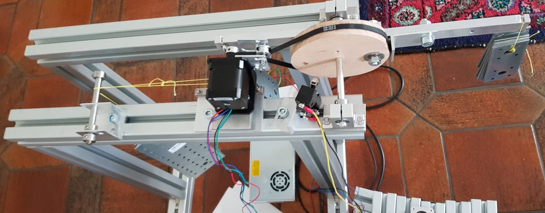
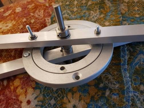
This was my gear teststation
- left is the weight to change the tension of the belt, currently 3 kg. The wire is Spectra fishing line. It does not tear, but the knots are critical. 3kg falling down is not fun.
- middle the stepper on a hiwin linear guide
- the stepper pulley with two deflection pulleys (they were needed to hinder slipping)
- the big wheel *) without teeth, with a stopper against slippage. This worked very good and allows open loop belts in the future (cheaper and easier to assemble)
- left arm for counterweight
- right arm for weight
- endstop in front
*) the wheel is so "unround", because I tried to round it with a band saw. I cannot recommend band saws for this task. They bend while sawing... I'll use a router for the next wheel.
-
@tony73
Hello, I am currently designing how to proceed with my prototype.I found the following ball gearing based plate:
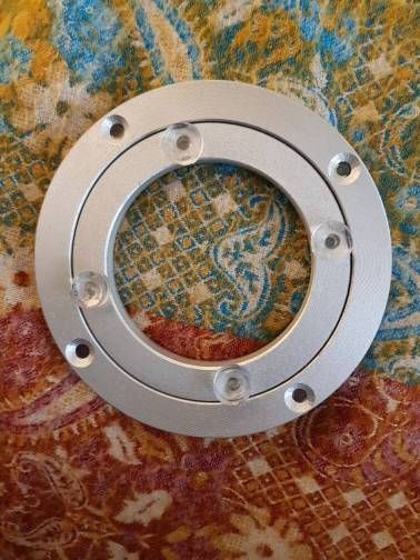
About 12 EUR for 120 mm or 255 mm diameter, a bit more for 300 mm, material aluminium. With a 20 teeth pulley at the stepper the 255 mm version will give a ratio of about 1:20.If the rings are pressed a bit sideways, they have no play. This should be a good hinge, with being a pulley at the outer diameter at the same time.
I wondered how it is built and how the two rings are assembled together, because there is no seam anywhere. I bought one and here is the solution:
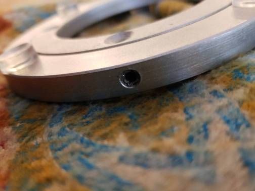
Throught this hole the balls are loaded/unloaded. Interesting. I damaged an allen key trying to open it, so I will bore a second hole.
If quality is too bad, I will replace the balls and hone the inner grooves a bit.My calculations are finished now regarding weights*) and gear ratios needed for the axes, I'll start building it now.
*) more exact: I want the torques of the axes to be 0 in sum for each axis, being torque at right and left of the axes being the same. Most demanding is finding the balance for axis 3.
-
@JoergS5
Hi! and very similar to a cross roller bearing, are the balls made of metal or plastic? after the tests you did, what reduction ratio do you want to use for the 5 axes 1/20? I will you use different ratios for each axis? I am designing a worm gear reducer, example:
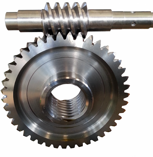
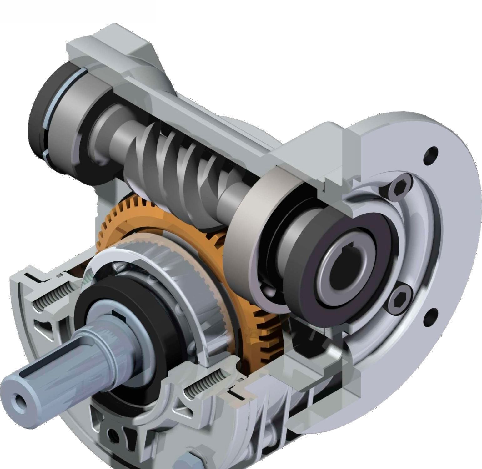
only a lathe will be needed to build it, with a method that will be simple (as far as possible) with the advantages that when the stepper motor is switched off, the arms will not be able to move and therefore will not fall, the reducer body will also act as a union joint between two arms, the great difficulty is the juxtaposition between the worm and the gear which must be zero! to have no game!
-
@tony73 the balls are steel ball. From what I see, the diameter is similar to the ones in linear guides.
I propose that you use worm drive and I the belt solution and we compare the two solutions and take the better of the two. The worm drive's prevention of falling down is a big advantage. We can mix the two solutions, because they have different advantages and disadvantages. For Axis 1 a belt solution may be best, axis 2 and 3 the worm drive. Axis 1 with the "cross roll bearing clone" has the advantage of an open space in the middle, where wires/filament can be routed through.
I will try 1:20, because the simplicity, but if is not sufficient, I can add the 1:3 resulting in 1:60.
-
@tony73 I tried the hinge with the rotating plate now, it is very stiff:
The play can be finetuned with the screws. I can put the elements even closer together when I get countersunk screws.
Edit: I was receiving other plates now, they have very different quality. The 300 mm diameter one is not round and I will have to rework him. Some have too much play. Some are good. And some don't have the boring holes at the correct position (opposite through the center)...