Duet3D Logo Duet3D
    • Tags
    • Documentation
    • Order
    • Register
    • Login
    1. Home
    2. JoergS5
    • Profile
    • Following 0
    • Followers 15
    • Topics 36
    • Posts 2,386
    • Best 294
    • Controversial 0
    • Groups 0

    JoergS5

    @JoergS5

    Interested in 3D print, robotics, woodworking, painting, solar energy.

    363
    Reputation
    338
    Profile views
    2.4k
    Posts
    15
    Followers
    0
    Following
    Joined Last Online
    Website www.joergschnur.de Location Germany Age 61

    JoergS5 Unfollow Follow

    Best posts made by JoergS5

    • RobotViewer DWC plugin

      I reread my documentation about setting up a robot and its DH parameters last week and must confess - I had problems to understand what I wrote a month ago. Setting up is complex and one can get confused fast.

      So I thought about to help creating robot parameters visually base with the help of a DWC plugin.

      Here it is, the first version of a working version to display a 6 axis robot configuration, based on Denavit-Hartenberg parameters, as described in https://docs.duet3d.com/User_manual/Machine_configuration/Configuring_Robot_DH_parameters

      The plugin runs in DWC 3.4.0 and I tested it on Mini 5+.

      The plugin is stored in github at https://github.com/JoergS5/RobotViewer, the downloadable and directly installable plugin is in the dist subdirectory.

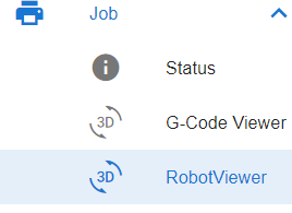
      After installation, a refresh in DWC was needed, then it was added to the Job folder:

      robotviewer1.png

      On the right is a visual representation of the robot:

      robotviewer2.png

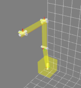
      The robot can be turned and zoomed.

      The buttons are:

      robotviewer3.png

      • my PC is slow, so freeze allows to freeze the screen, so GPU is near 0%
      • Gitter show or hides the coordination gitter
      • Coords shows or hides the three axis coordinate system in the order of RGB: red X axis, green Y axis, blue Z axis. Rotations or prismatic movement is always around the Z axis (blue one)
      • Axes show or hide white tubes representing the axes. For prismatic joints, the visualizations needs improvement
      • Arms shows or hides the arms
      • Angles: change angles for the 6 joints
      • DH show or hide DH parameters: type rotary/prismatic, A0 is the base, DH1 to DH6 are the DH parameters, Tool ist tool XYZ
      • Gui is currently only to change the screen size of the main screen

      The first version has its weaknesses, I am still learning the used javascript libraries. I plan to improve the following points:

      • save and load to 0:/sys/robot.g the parameters and settings, so they can be included as macros into config.g to set robot properties
      • visualize min/max/home angles (rotational) or mm (prismatic) joints
      • full screen mode like G Code Viewer
      • tool offset better visualization
      • flexible number of joints (between 2 axis to 7 axis)

      A bit more in the future is:

      • animate G1 moves
      • animate an imported G-Code file
      • verify inverse kinematics of the main firmware by asking and visualizing the segments
      • visualization of the workspace and singularities
      posted in Plugins for DWC and DSF
      JoergS5undefined
      JoergS5
    • RE: Robotic kinematics

      I have time in May and June now to proceed developing robot kinematics. The order is

      • 4 axis parallel (the black robot arm), probably as a quick-and-dirty approach first for @YuriConfessor
      • DWC plugin to design and analyse a given model
      • CoreXY/Prusa/Cartesian 5 axis AC and BC
      • 6 axis robot
      • testing whether Qt is a possibility for a designer/slicer
      • elaborate tool design. My personal priority is using robot for CNC, so I'll work on support for different tools (tool shape etc).

      I'll use 3.5.1 as basis.

      posted in MultiAxis Printing
      JoergS5undefined
      JoergS5
    • RE: JoergS5's CoreXY 5 axis (robot kinematics)

      The next prototype will be a CNC 5 axis, and now may be a good moment to share my experience with manual tools, so I gathered some ideas:

      one of the most valuable tools I have is this one, together with a good caliper:

      graingranulate.jpg

      which allows more exact graining(my model: Soba Optical Center Punch).

      The next hint is to measure bought parts, there are surprises sometimes:

      ringdefect.jpg

      and sometimes a part which has a documented thickness of 31.5 mm has only 30.0. Aluminium extrusions are not flat in most cases. There's a reason why CNC people route them before using. Your construction should not rely on extrusion's flatness (if you have not routed it):

      extrusionflatness.jpg

      using a hair angle or hair lineal, great tools to check flatness.

      An aluminium part is not necessarily 20 mm, but sometimes 20.2, and not 2 thick, but 2.15. Measuring deepness of the carriage holes is also a good idea (all holes), because they differ, to choose the right screws.

      Talking about measuring, this is one of my favorite book titles:

      measuretwice.jpg

      I bought some waste aluminium for 3 EUR/kg, and my next hint is to practice a lot, using the failed attempts for washers and the like. After graining, boring etc many parts you have gained experience. Then it becomes quite easy to make a part.

      One very useful tool is a band saw, I use a Proxxon MBS220, which is enough to saw 6 mm alu. But be careful, the parts become hot after sawing, especially with big drills like a drill to bore 16 mm holes (use coolant like cutting oil).

      I try to achieve stable structures by using aluminium 3 mm or thicker, creating closed objects. I always try to use two connections to hold parts or shafts by ball bearings to hinder rotation or tilting.

      A special topic is deburring, which I often do between single holes, because they level the parts wrong when not doing it (the next hole is not vertical any more). Burrs look ugly, but more important, they prevent good connections or alignment. For high precision, I use cone drills for final processing of a hole.

      I prefer nut stones with spring, because they can be inserted without disassembly of the frame. Hammer stones alway rotate into the wrong direction, but sometimes they are needed because they need less space.

      An example of a failed nutstone usage is here, where the angle recess conflicts with the nutstone height. The connection is very loose as result:

      nutstonewrong.jpg

      When designing parts, holes to access screws (eg the pulley screws) is important. At the same time I try to make closed structures for stability.

      The carriages of the linear guides need to be protected against moving over the guide edges. I you already searched the balls, you know what I mean. Even worse for ballscrew.

      For rotating parts, I often insert washers. This special 8x12x0.5 washers between the F608 make the connection only at the inner (not rotating) part, not the outer, so the F608 can rotate without friction:

      washer.jpg

      Talking of washers, the old locking washers DIN 127A, 127B, left were withdrawn because they are unreliable:

      lockingwasher.jpg

      I use the right one DIN 6797 Form A, but there are many options with different capabilities like DIN 6797 form J, 6798 multiple forms, 7980 etc. I choose 6797 because they shall protect against vibrations.

      posted in My Duet controlled machine
      JoergS5undefined
      JoergS5
    • RE: Spindle nema 34 duet 2 wifi

      Firmware organizes all axis movements in time frames (X moves n mm in 0.1 seconds, Y m mm in the same time etc.). A continuous movement doesn't have a time frame (because it's infinity time), so it's a problem.

      A solution could be to add a separate FreeRTOS task which makes the continuous movement for a (stepper-)motor by generating own stepper signals without any time frame planning. It would run isolated from all other movements, but this needs to be added to the firmware, something for the wishlist.

      posted in CNC
      JoergS5undefined
      JoergS5
    • RE: Duet 2 Hangprinter, 5-bar Scara, Polar, Rotary Delta kinematics

      @dc42 if you decide to remove those kinematics from core RRF, I offer to take a lead for source and documentation for 5-bar scara, 5 axis robot, 6 axis robot and later this year for stewart/hexapod kinematics.

      My proposal are dedicated github repositories on Duet3D (so the repositories can be found) for those kinematics with source and binaries, so users who want to use them can easily install them. I propose to offer binaries for Duet 3 based hardware (6HC CAN, Mini Eth, Mini WiFi, 6XD) for main releases and maybe for a part of the beta versions.

      posted in General Discussion
      JoergS5undefined
      JoergS5
    • RE: Robotic kinematics

      Some time since last update, so I want to give some update information. Had Covid and recovered, hope you are all well too.

      Robot kinematics will be included in RRF 3.5, after talking with David and Tony. I have agreed to have a working version end of August, so the integration will start after this date.

      I am currently working on

      • performance optimizing and testing
      • implementing additional kinematics like CNC 5 axis and 4 axis palletizing robots which are built like ABB IRB 460
      • documentation. Starting point is https://docs.duet3d.com/User_manual/Machine_configuration/Configuring_RepRapFirmware_for_a_Robot_printer and I tagged the documents with robot tag, currently 4 documents. Detailed descriptions e.g. of orientation, RobotViewer, Config. Please ignore misspelling, but if you find logical errors, please tell me to correct it
      • still working on a good prototype, but this takes eternal
      posted in MultiAxis Printing
      JoergS5undefined
      JoergS5
    • JoergS5's CoreXY 5 axis (robot kinematics)

      I've built my CoreXY 5 axis now, 90% finished (it will never end, I have new ideas every day).

      This is a build with experimentation as design goal, not productive use or a high WAF. If someone wants to have such a machine, using Voron and modify it (like BrendonBuilds) will probably be the better choice. I've reread the very useful Mark Rehorst's blogs about his CoreXY. I tried hard to not be member of his hall of fame (a collection of CoreXY design errors).

      corexy.jpg

      Aluminium 45x45, F608 ball bearings, THK linear guides.
      There are two carriages on the THK linear guide each. I'll use the second for a router solution for abrasive work.

      The reason to build it is to

      • verify the robot kinematics firmware
      • give examples how to configure, home and print
      • discuss problems with optional recreation

      The A and C axis are belt gear based:

      aaxis.jpg

      caxis.jpg

      The C axis has long belts and long distance between A and C axis intentionally to check the firmware correctness. It will be better for productive use that the C axis is above the A axis with a counterweight (eg stepper) below it, so it's balanced to avoid falling down when steppers power off.

      The belt gears are 12/60 teeth in two stages each, so 1:25 each.
      To calculate the distances of the gear axes, I used https://www.technobotsonline.com/timing-pulley-distance-between-centres-calculator.html

      The C axis with 8 mm steel rod is too weak, it bends too much for my taste, I'll have to use an alternative or support it.

      The X axis has a linear guide below it. In my current understand, thermal expansion is not the main problem why it's necessary, but one cannot calibrate the two rails exact enough (few micrometers necessary in all planes), so they would stuck fast:

      xaxisRight.jpg

      The clamps for the XY belts were complicated, there are always screws in the way! I'll use Mark's belt clamp probably in the future:

      beltclamp.jpg

      XY belt tensioner is using linear guides and weights. I can fix the position by the clamp. It's good to have a protection against wire tear:

      belttensioner.jpg

      The weights can be changed to calibrate XY. Better than those steel weights would be something like high density gold bars, but I didn't have them on hand. The wire is fishing line 40 lbs. I will probably use this construction to use weights for other tasks too, where I need a defined force.

      The "print bed" is polystyrol and a paper hotend to avoid damage while testing:

      printbedPS.jpg

      Some first test results are:

      • when A axis is rotating, there are crashed with the frame which are unexpected. To build in collision detection may be a good idea
      • same with A rotating and RTCP XYZ compensation means that eg Z remains at its position, but the motorPos not! A configuration of motorPos range may be necessary to avoid the crash.

      I used 2 steppers for Z axis:

      zaxis.jpg

      The reason is, I tried the belt solution to connect the two axes, but the belts are in the way of the rotating A axis. Routing the belts around the area was a complex task. The second reason is, the two steppers for Z will allow a small tilting (at AC, this means a third rotating axis around B), this may be useful in the future for slerp 6 axis based (Yan, Jeng, Chieng Five-Axis Slerp for Tool-Orientation...).

      To test different Duet boards, I used Wago connectors:

      wagoconnectors.jpg

      Crimping was again my "favorite task".

      I search a solution to allow free rotation of the table. I'll probably design something similar to "RS Pro 176-0897" for the bed heater.

      That's for the moment. I am currently testing my setup and will describe it later, same as my thoughts about homing and then trying FullControl for sample prints.

      I'll make new bins this evening with my firmware corrections for Mini5, 6HC and Duet2.

      One hint at the end: set stepper speeds low while testing, so you have enough time to press the emergency stop button...

      posted in My Duet controlled machine
      JoergS5undefined
      JoergS5
    • RE: Are you a mobile or desktop app developer?

      @zapta dear zapta, are you still interested in a DWC plugin for this motor analyzer? I can begin developing it next week (slowly). Whether I can manage to use bluetooth without https or how to find a workaround, I am unsure and have to check.

      posted in General Discussion
      JoergS5undefined
      JoergS5
    • RE: Robotic kinematics

      I've finished the robot 6 axis inverse kinematics now with Paden-Kahan algorithms, the time measured on a 2 GHz laptop is 30 microseconds to get the 8 solutions. Maybe factor 10 for a Duet. Optimization is possible by calculating only the nearest angle solutions. (maybe in Limitposition calculating all solutions, and in segmented calculations only one solution).

      I'm constantly updating the screw theory page, especially the literature links, if someone is interested following the underlying theory.

      Next will be to implement linear axes with screw theory for the CNC/Prusa/CoreXY like 5 axis. Then I'll try to implement PK2 Dimovski et al solution (for 6 axis robot first three axes).

      posted in MultiAxis Printing
      JoergS5undefined
      JoergS5
    • RE: JoergS5's CoreXY 5 axis (robot kinematics)

      I've installed a new longer (18 cm) hotend for less crashs (see below)

      hotend2.jpg

      and created new binaries and checked in the current code. I rewrote the RTCP code and tested it. This builds have all limits like M208, angle and speed limits deactivated.

      To give an impression, my current configuration part for setting robotic is:

      M669 K13 B"CoreXY5AC"
      
      M669 A"C=-179:179:0"
      M669 A"A=-179:179:0"
      M669 A"Z=0:300:0"
      M669 A"X=-150:150:0"
      M669 A"Y=-150:150:0"
      
      M669 C"C=0:0:1:0:0:0"
      M669 C"A=1:0:0:0:140:-70"
      M669 C"Z=0:0:1:0:0:0"
      M669 C"X=1:0:0:0:0:0"
      M669 C"Y=0:1:0:0:0:0"
      
      M669 C"Mnoap=1:0:0:0:1:0:0:0:1:0:0:0"
      M669 C"Mreference=0:0:0:0:0"
      
      G92 X0 Y0 Z0 A0 C0
      

      The most important is the Mnoap endpoint. If I home all 0 values to this endpoint, calibration is easiest. A good endpoint is the middle of the bed, on the Z0 surface of it. This is cartesian coordinate (0,0,0) also. The axis points are next important and the need to measure them more exactly is an open task.

      BTW I really don't understand why Z is axis orientation (0,0,1), because the positive Z should point down. Another point is that the Voron is opposite direction of traditional CoreXY: Voron platform down means less distance hotend-endpoint. Traditional bed up means less distance. So Z axis orientation may need to be opposite for Vorons.

      With G92 I set homing for all axes, and the M114 Count values are 0 each because the endpoint is 0. Controlling motor and machine positions is easier.

      RTCP seems to work ok, only C has some inexactnesses. But I suspect this is the missing exact calibration. A, X, Y and Z move nicely RTCP according to the AC rotation. One open issue is at X0Y0, where the rotation by C is undefined for the inverse kinematics. I currently set rotation to 0, but the new C angle is stored.

      The tool length parameters are removed, because it's only necessary to change the endpoint when changing tools. This is imho safer than trying to detect a tool change.

      I've moved the bed deeper, because by testing A rotation, I constantly crashed the Z axis at the top. A terrible noise. Talking of A, I have to fasten the pulleys better, they were loose after a few hours. I'll connect the pulleys by screws and make notches into some shafts.

      I added a reporting of the current configuration. When M669 is called (after setting robotic K13), it is output to the console, e.g.:

      === M669 K13 current config ===
      numOfAxes 5 axisTypes RRPPP chain CAZ_corexy(XY) (normal CAZ.. special XY)
      axis C ori: 0.00 0.00 1.00 point: 50.00 -50.00 0.00 angles min/max/home: -179.00 179.00 0.00
      axis A ori: 1.00 0.00 0.00 point: 0.00 120.00 -75.00 angles min/max/home: -179.00 179.00 0.00
      axis Z ori: 0.00 0.00 1.00 point: 0.00 0.00 0.00 angles min/max/home: 0.00 300.00 0.00
      axis X ori: 1.00 0.00 0.00 point: 0.00 0.00 0.00 angles min/max/home: -150.00 150.00 0.00
      axis Y ori: 0.00 1.00 0.00 point: 0.00 0.00 0.00 angles min/max/home: -150.00 150.00 0.00
      Screw values:
         reference angles/positions:  0.00 0.00 0.00 0.00 0.00
         endpoint axis X: 1.00 0.00 0.00
         endpoint axis Y: 0.00 1.00 0.00
         endpoint axis Z: 0.00 0.00 1.00
         endpoint point: 0.00 0.00 0.00
      special kinematics set: CoreXY
      abSign: 0  (0 means A (B) positive angle preference)
      cache used: 80 maximum: 200
      

      I'll add a summary check for completeness.

      posted in My Duet controlled machine
      JoergS5undefined
      JoergS5

    Latest posts made by JoergS5

    • RE: Spirograph emulator with Duet2

      @o_lampe said in Spirograph emulator with Duet2:

      Would it be possible to add a rotary tool to a CoreXY frame?

      The current RRF firmware calculates tools as being vertical, non rotating, non moving, describable with fixed XYZ offets (mesh compensation, baby stepping, tool changer depend on this linear offsets, e.g.).

      To avoid this limitations, the tool itself can be divided into a part like a moving/rotating axis and a fixed endpoint which can be dimension zero. With robotic kinematics, you simply add this additional axis to the chain. Forward kinematics is easy to calculate, but inverse kinematics (calculation from world coorinates back to motor positions) can be complicated. It depends on the implementation and axis positions whether it's complicated or not.

      If you design your tool as a spheric design, so that some axes cross in one point with the axes before, the inverse calculation is easier. When you have a prototype and description, we can solve it together.

      posted in CNC
      JoergS5undefined
      JoergS5
    • RE: Kinematics for 5-axis CoreXY printer

      @tcpl this is an interesting design. I will develop the firmware to support it.

      The behaviour of the rotary axes depend on whether they are connected to the starting point (e.g. connected to the bed) or the endpoint (hot end or drill). Connected to one or the other changes the direction of the rotation. I will probably change the definitions and configuration to a general description. I will have to think about how to define it with the M669 parameters easiest.

      posted in MultiAxis Printing
      JoergS5undefined
      JoergS5
    • RE: Kinematics for 5-axis CoreXY printer

      @tcpl are you sure it is AB type? This would mean the rotary axes are parallel to the X and Y axes. I've not seen this type until now, so I only implemented and tested AC and BC. Do you have a picture or drawing to verify the rotary axes types?

      I will continue mid may to develop and can add AB if you need it.

      posted in MultiAxis Printing
      JoergS5undefined
      JoergS5
    • RE: Robotic kinematics

      I'm back with robotics. My partner passed away, I had to mourn, I have a new partner now since a few months, she will be on vacancy alone mid to end may. So this will be the time frame when I will work on robot kinematics again, based on RRF 3.6.

      I will implement an idea I had last year and started implementing some time ago. Robotics solutions are be very different for forward and inverse kinematics. So I thought about a generic approach:

      • a forward chain to combine different drive movements into one movement chain, with one or multiple solutions
      • a backward (inverse) chain with the result of none to multiple solutions
      • forward and backward chains are stored in arrays which can be set by parameters with M669. Kinematic code will simply process the chains
      • to find the chain solutions, the user can think it through mathematically and set the parameters or he can use the to-be-programmed Qt based program to set solutions or simulate them and compare to measurements of the prototype
      • the chain elements are code fragements to implement mathematical solutions. The mathematicsal solutions can be augmented in future releases when necessary

      That's my plan.

      posted in MultiAxis Printing
      JoergS5undefined
      JoergS5
    • RE: 4 axis palletized robot arm (robot kinematics) for 3D printing

      @Nakcam it's all fine with your information, I have "only" a time problem. I can proceed tomorrow for a few hours.

      posted in MultiAxis Printing
      JoergS5undefined
      JoergS5
    • RE: Need help with 5 Bar SCARA configuration

      @DoodleCube said in Need help with 5 Bar SCARA configuration:

      it seems RRF3 on Duet 2 stopped supporting 5 bar

      there are flags in RRF to turn on or off those "exotic" kinematics, so if you're able to compile it yourself, you can turn it on for Duet 2.

      Pins.h
      '# define SUPPORT_FIVEBARSCARA 0
      Set this to 1.

      posted in Firmware installation
      JoergS5undefined
      JoergS5
    • RE: 4 axis palletized robot arm (robot kinematics) for 3D printing

      @Nakcam thank you for clearification.

      Robot kinematics is based on a chain of the actuators: axes with position and orientation and arms between them. The endpoint is just an additional arm without axis. So you can add axes at the beginning and end, but inverse kinematics must be able to calculate it. Your rotating base is included in the 4 axis parallel robot type. Your linear axis at the beginning is something additional. The robot type sometimes has an additional actuator at the endpoint, for rotation of the end plate or for a gripper.

      I proceed tomorrow to develop, because I feel that I have understood it now. I will develop with the blue line being curved optionally. (not a straight line between the three hinges of the blue line).

      posted in MultiAxis Printing
      JoergS5undefined
      JoergS5
    • RE: 4 axis palletized robot arm (robot kinematics) for 3D printing

      @Nakcam sorry for the delay. I had a family problem, I'll try to proceed.

      I want to clearify, please tell me:

      parallelDetail.jpg

      My understanding is:

      • 1 is the first actuator
      • 2 is the second one. Together they define through the parallelogram the blue arm and the lower end position, lower hinge
      • 4 (the second arm in back of 1) is unclear for me: is it just to stabilize or has it a movement function?
      • 5, 6 and 7 define the upper endpoint in respect to the lower endpoint through parallelism

      Is my understanding correct?

      Comment in advance to the linear rail where you plan to install it on: this fits perfect into a calculation chain, but you have 4 actuators and 3 degrees of freedom (xyz, orientation always the same). This results in indefinite solutions (you can reach a point with different combinations of linear rail and the 3 actuators), i.e. for a desired position there must be installed a strategy. E.g. if the planned coodination is out of reach, move the linear rail to the middle of the new next work area. This movement should not be in a move, but between moves. I want to make something similar: some (5 or 6) robot arm installed on a linear rail at the wall.

      posted in MultiAxis Printing
      JoergS5undefined
      JoergS5
    • RE: Need help with 5 Bar SCARA configuration

      @droftarts said in Need help with 5 Bar SCARA configuration:

      looks like the kinematics expect the X actuator on the left

      the X parameter is for the first and second actuator's X coordinates, Y for the Y. In the documentations example: "E.g. X0:100.5 Y0:0 means 100.5 apart and both on the y axis." makes it clear. But this may be an example of confusing documentation...

      The first actuator should be on the left. Otherwise some details like numbering of the work modes will be wrong.

      @DoodleCube Stepper orientation: the definition is the axes are pointing out from the plane to you and then positive degrees are a rotation counterclockwise. So with H2 single actuator relative movement, a positive rotation must be counterclockwise. e.g. G91 G1 H2 X5 should rotate the first actuator counterlockwise by 5 degrees. Best start with small values and when you have confidence, use a value where you see whether the steps/degrees are correct, e.g. with a 90 degree rotation.

      posted in Firmware installation
      JoergS5undefined
      JoergS5
    • RE: Need help with 5 Bar SCARA configuration

      @oliof said in Need help with 5 Bar SCARA configuration:

      H2/ direct motor moves happen in degrees

      you're right. This may explain my strange experiences.

      posted in Firmware installation
      JoergS5undefined
      JoergS5