Robotic kinematics
-
@tony73 your harmonic drive looks promising. Using this gear type would be the best solution for the robot imho.
I have bought some used original ones, they have less teeth heights. I suspect this makes it easiert to flex the flexspine.
-
@tony73 my status is, I finished axis 3 and 4 with gear and fixing the open belts, here are images:
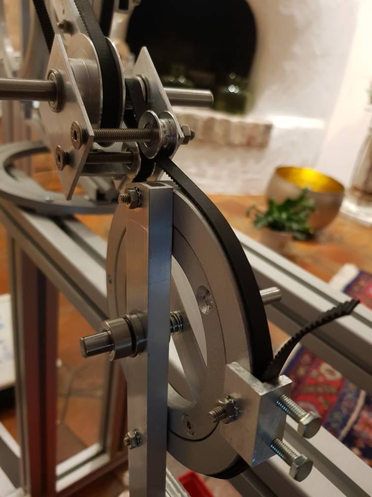
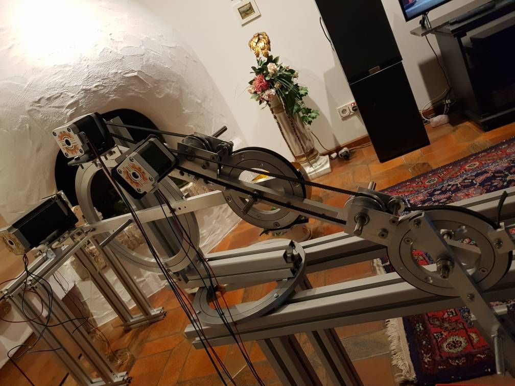
An open issue is how to get good belt tensions.
The arm balances are working good, protecting from falling. -
too long teeth and a fact that I had noticed too! the wave generator, it must definitely be less elliptical as possible! with shorter identi, let's say cut in the shape of a trapezoid, you can definitely make a wave generator not very accentuated more like a circle! groped to replicate it in steel and perhaps madness! but to have an experience and out of curiosity, I'll try! , About 2 years ago I had printed one in abs with a ratio of 35/1 for a neima 23, it works but in plastic you cannot expect to have a zero clearance! if I have not misunderstood! you bought one! do you have a front photo to see the teeth? anyway congratulations for the work on the robot! when do you think you can try it?
-
@tony73 I can make photos in a few days (should be possible during this week). I bought some harmonic drives used, but even used they are very expensive (not less than 200 EUR/$ each). It would be very good if you can build a good working harmonic drive!! I'll design arms, hinges, stepper positions in the third prototype for them. If you can make them with big diameter (range 70-100 mm diameter), this would give the arms good sideways precision. But to find the best method and properties, a 33 mm diameter is ok of course for the first 100 (
") ) iterations.
) iterations.Prototype 1: precision of the holes for the big wheels is very critical for smooth rotation, so I'll rebuild the arms, because I was not precise enough, they stuck at some angles. And axis5+extruder+hotend is open to be built. But no design problems are open, it "only" needs some time. Then I'll have the first prototype.
The belt gears are easy to produce, so it may be a good solution for someone who has no specific tools like routers, CNC etc. But the belts flex a bit, a harmonic drive would be much better.
I am prepared to build several prototypes to find the best solution and provide alternative build options. In the second prototype I'll try to build the smallest possible robot, based on Nema 8 steppers.
Current planning:
- 1: 45x45x45 cm build, belt gear based, low precision
- 2: as small as possible, belt gear based, maybe R1 mode
- 3: 45x45x45 cm build, harmonic drive based, high precision
- 4: as large as possible, testing bending parameters, for wall painting eg, rail support
-
@tony73 I think I was wrong with the teeth of the harmonic drive, here are the images of outer and inner ring. If you need to know the company, please chat me, I don't want to publish it here:
outer:
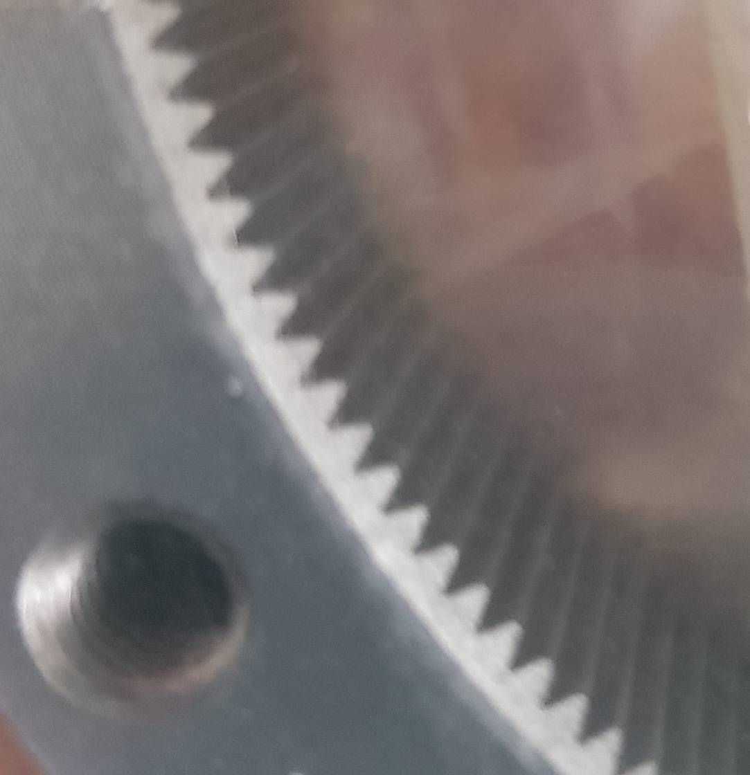
inner:
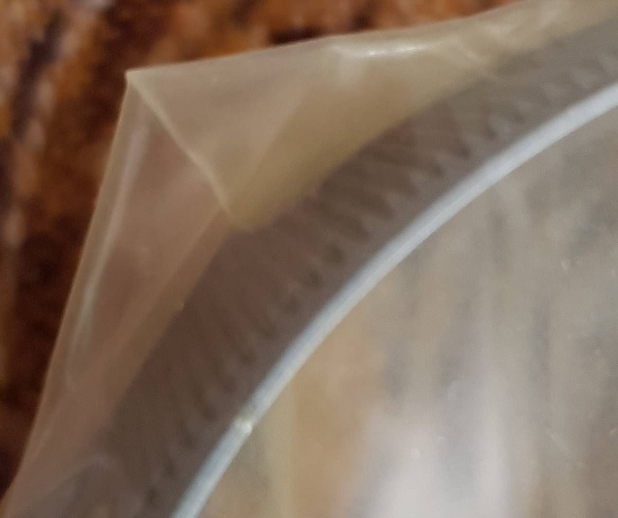
The quality of the images is not good, because they are in their original packaging, but I hope you can see the shape of the teeth.
It's a special kind of harmonic drive: two outer rings with teeth and one flexspline with only the ring (without the part at the side). It is used to adjust the angles of two axes (differential gear).
The company advertises that nobody was able to copy the quality, although the product is available since many years. So I expect that the teeth is not the important factor, because by buying one of it allows simple copying. I think important factors are
- material of the flexspline, being flexible, but at the same time can bend thousands or millions of time without going broken
- lubrication will be important also
- high precision of the parts
The material of Hylite could be a candidate for the flexspline, because it can bend may times. Hylite uses polypropylene. But abrasion could be too high.
-
This post is deleted! -
@JoergS5
Hi! how do i chat with you? I would like to understand how it is made ľ harmonic drive you bought! and complete with crossed roller bearing? as I said, replicating it in steel is madness! but not impossible! the tricky part will be hardening the flex spline and producing more than one harmonic drive in a reasonable time!
and like this?

-
@tony73 this is exactly the model I meant. It's the only one which I have opened, the other ones are closed, so it's not easily possible to show the teeth. But the differential gear are not meant for the robot. Maybe it's usable for robot, I'm not sure. The flexspline is easier to produce than the normal one, and there is no tension between the teethed part and the vertical part. I'll have to check whether I have the wave generator for this type. There is also a 2 part case around the parts of the picture.
The wave generator is normal ball bearing (unbalanced of course). Cross roller bearing was a separate idea, not harmonic drive, with something called ServoBelt Rotary, patented by Everman and a partner of him. ServoBelt Rotary would be a nice solution for Axis 1, harmonc drives more for axes 2 to 5. Axis 1 has the hole robots load vertical to the bearing, I expect the cross roller bearing better than the harmonic drive in respect to load. (But the ServoBelt has no gear inside, it may be better to use harmonic drive for all axes).
If you want to DIY the wave generator, please be aware that when buying balls, they have tolerance classes: G2/G3 best, G10 very good, G100 good quality, taking G10. Maybe it's easiest to produce a wave generator by bending a normal ball bearing a bit, with loadlifter.
The tolerance classes are inside one sample that you buy. E.g. buying 100 balls, they have tolerance G10. But buying another 100, they have only G10 to each other, not to the first sample. In other words: buy together what you need, and some more (I always loose balls when disassembling lol).
Chatting is done at the top menu, the bubble symbol. I prefer normal blog discussion, then everybody can see the information. But in this case it's an exception. To start a chat, open the profile of the other user, then the three dots ..., top entry is start a chat. I already sent you an information by chat.
-
@tony73 I found the wave generator now.
The diameter is between 60.6 and 62.0 mm, so only 1.4 mm difference. The balls are about size 6 mm (I cannot measure exactly).
The generator is built by two ball bearings, which are only connected by the axis.The flexspline teeth are total high 1.4 mm (including inner ring) for teeth high less than 0.7 mm, teeth distance 0.7 mm, so this fits good to the generator.
-
@tony73 https://www.bengtssons-maskin.se/uploads/extrafiles_file_2.pdf page 23 top is also a good idea, combining worm drive with a big wheel.
But if possible I would prefer harmonic drive because of the zero backlash.
-
@tony73 I found a scientific article about flexspline:
http://fluid.ippt.gov.pl/bulletin/(58-4)683.pdfmaybe of interest for you, what could be helpful for a longer life of the parts.
-
@JoergS5
good morning! how is the work on the robot going? -
@tony73 hello, I am currently working on gears of axis 1 and 2. I will use Nema 17 with axis 2 now, so I can use every Duet hardware with the robot (2A max for every stepper). I made improvements to belt tensioning and the weight distributions of axis 3 and 4. I will start today with axis 5 + extruder + hotend, maybe I can make the first print tomorrow.
In the meantime I made some investigations about harmonic drive. Maybe it's possible to implement without metal, there were some promising attempts, like https://www.youtube.com/watch?reload=9&v=t4hW6lZYaQk and connected usage with servo https://www.youtube.com/watch?v=tVlKTpKXCsY
It looks nice, but jerky at some movements. I think precision is key.
The attempts on youtube and thingiverse have very different quality. -
I think making cycloidal reducers yourself is preferable to harmonic drives. The flexspline is hard to make without metal and more often than not you end up with a reducer with very low durability and torsional rigidity. Cycloidals on the other hand use just rigid components and are a lot easier to make with printing. And offer a lot more torsional strength.
-
@roiki11Did you make some yourself, this would be interesting. What I know is that the gear ratio is limited in the range of 1:8 in the most examples I saw. So they are often combined with an added 1:3 belt gear between stepper and cycloid gear.
-
@JoergS5
Yes I've made some. Somewhat big with 72.5 reduction.The reduction ratio is not limited at all since you can use multiple stages. You can also get 30:1 reduction quite easily on a single stage too. Though if small size is a priority then that can limit the cycloidal ratio.
-
@roiki11 are they open source and you can share it please if possible. If not, maybe you can provide a hint where to start or whether you started development from an example. And did you make them 3D printed or with metal?
There are some thingiverse and youtube builds, but one never knows which ones are good quality and which not, unfortunately.
The robot hinges are better with bigger diameter imho, because they give added sideways stability. I think 10 cm diameter is ok for a printer for print area 40 or 50 cm each dimenstion.
-
@JoergS5 said in Robotic kinematics:
@roiki11 are they open source and you can share it. If not, maybe you can provide a hint where to start.
There are some thingiverse and youtube builds, but one never knows which ones are good quality and which not, unfortunately.The robot hinges are better with bigger diameter imho, because they give added sideways stability. I think 10 cm diameter is ok for a printer for print area 40 or 50 cm each dimenstion.
The one I'm working now is about 140mm in diameter. It's not completely finished yet since I have some parts to print and final fit. It's completely working though. I can link the fusion file sometime.
You can also check opencyre. it's a pretty good design. There's also a
Script for fusion for generating the cycloidal gears. I used that which made the design work really easy. https://github.com/mawildoer/cycloidal_generatorJust remember that the reduction ratio is "<number of pins> - 1" or the number of lobes on the rotor.
-
@roiki11 thank you for the links, I will give cycloidal a try. I agree with you that the cycloidal drive is easier to build.
Do you plan to build a robot with it also?
-
@JoergS5
good morning! were you able to try the print?