Active Y Endstop disables X & Z endstops
-
Hello all,
To expand on the subject line. If the Y endstop is hit/active the other endstops become disabled. Or stated 'inversely' way, if the y ednstop is not active the X & Y endstops function as expected, and can simultaneously.
A functional example. If I home Y first, then X & Z, X & Z will physically crash at the ends of their travel. As soon as I move Y off its endstop, I can home X & Y.
I can home X, then Z, or vise-versa, with no issues. As soon as Y is active, X & Z become useless.
This seems odd to me.
Endstops are wired independently. However the difference between them is that Y is a physical snap-acting switch (at the moment) and X & Z are hall-effect. Can't figure why this would be an issue as they are independent.
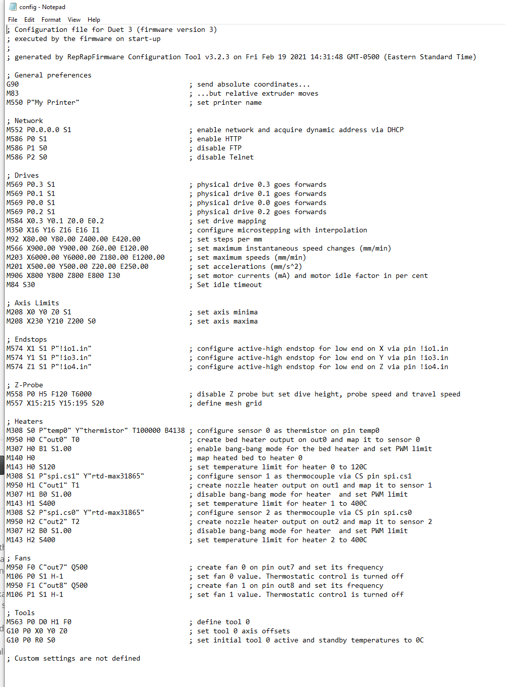
Gcode setup here:

I'll keep investigating.
Thanks for any help.
-Peter -
Well it is not supposed to do that.
I'm using firmware 3.2.2 and before that 3.1.1 and I know the end stops didn't care what other end stops were doing.
What version of firmware are you using? Version 3.2.0, at least, had a problem with end stops.
Frederick
-
I believe I'm using the latest FW.
I just went through my gear and found another hall-effect sensor, so all 3 are the same. All three are playing nice now. Would love to know why, (if) having a different type of sensor was the reason (didn't change anything else)?
Thanks for replying and offering advice, it's appreciated.
-Peter
-
@customPrint said in Active Y Endstop disables X & Z endstops:
I believe I'm using the latest FW.
I just went through my gear and found another hall-effect sensor, so all 3 are the same. All three are playing nice now. Would love to know why, (if) having a different type of sensor was the reason (didn't change anything else)?
Being different shouldn't be an issue - I've used IR beam break sensors with mechanical micro switches without issue.
Perhaps you had a wiring problem with the unit your removed the was messing with the supply voltage to the other units?
Frederick
-
@customPrint said in Active Y Endstop disables X & Z endstops:
is that Y is a physical snap-acting switch (at the moment)
how did you wire the switch?
-
@fcwilt I agree 100%.
Granted none of them with a Duet board, but I have designed many electro-mechnical systems at work, that have a mix of sensors (inputs) and never a problem. This is the reason it's a mystery to me.
When it was hall-effect/snap sensors, they all worked 'independently' as described above. When I replaced to the final hall-effect, all I changed/flipped around, was which wires from the sensor went to Vcc, Gnd and io_in, but in the end, same pins being used at the same IO port.
At this point I'll continue my build and if something occurs to me to why, that I can test, I will and report back.
-
I'm using this sensor:
https://sensing.honeywell.com/honeywell-sensing-omnipolar-digital-hall-effect-sensor-ic-datasheet-ss351at_ss451a_ss551at_005917-4-en.pdfWiring to 3.3V, Gnd and ioX_in pins at the io port, via the upper left wiring diagram in "Figure 4. Wiring Diagrams" section of the PDF. I omitted the pull up resistor as in a few places, it's mentioned that there's one built in to the io port on the Duet. The sensor sinks the voltage, so ioX_in.
-
no i was talking about the switch which is causing the problem
-
@customPrint said in Active Y Endstop disables X & Z endstops:
@fcwilt I agree 100%.
I had some devices marketed as end stop sensors - I don't remember if they were micro switch or IR beam break - but they didn't work.
The colors of the wires were RED, BLACK and WHITE - so naturally I hooked RED to power, BLACK to ground and WHITE to signal.
No go.
There were markings on the little PC board of VCC, GND and SIG.
A bit of inspection showed that the cables that came with the units were wired incorrectly.
RED did NOT connect to VCC.
I don't remember now exactly what the wiring was but as soon as I noticed the error with RED I fixed the wiring.
Frederick
-
@Veti Ok. it's a simple mechanical snap switch and appeared to work fine when m119 queried, manual operated and 'multi-meter-ed'.
-
@fcwilt Right and understand what you are saying.
I built my sensors and mounts, so obviously, was following the wires closely. I ended up using ribbon cable that I had, so there's no color code, just notes stating what they are.
I would have done the same thing that you did otherwise.