Printing problem with filament or set up?
-
; executed by the firmware on start-up ; ; generated by RepRapFirmware Configuration Tool v3.2.3 on Tue Jul 06 2021 10:19:08 GMT-0400 (Eastern Daylight Time) ; General preferences G90 ; send absolute coordinates... M83 ; ...but relative extruder moves M550 P"Big Box 1" ; set printer name ; Network M552 S1 ; enable network M586 P0 S1 ; enable HTTP M586 P1 S0 ; disable FTP M586 P2 S0 ; disable Telnet ; Drives M569 P0 S1 ; physical drive 0 goes forwards M569 P1 S1 ; physical drive 1 goes forwards M569 P2 S1 ; physical drive 2 goes forwards M569 P3 S1 ; physical drive 3 goes forwards M569 P4 S1 ; physical drive 4 goes backwards M584 X0 Y1 Z2 E3:4 ; set drive mapping M350 X16 Y16 Z16 E16:16 I1 ; configure microstepping with interpolation M92 X160.47 Y361.26 Z1599.10 E185.0:291.30 ; set steps per mm M566 X900.00 Y900.00 Z60.00 E120.00:120.00 ; set maximum instantaneous speed changes (mm/min) M203 X6000.00 Y6000.00 Z180.00 E1200.00:1200.00 ; set maximum speeds (mm/min) M201 X500.00 Y500.00 Z20.00 E250.00:250.00 ; set accelerations (mm/s^2) M906 X800 Y800 Z800 E1200:1200 I30 ; set motor currents (mA) and motor idle factor in per cent M84 S120 ; Set idle timeout ; Axis Limits M208 X0 Y0 Z0 S1 ; set axis minima M208 X300 Y200 Z300 S0 ; set axis maxima ; Endstops M574 X1 S1 P"xstop" ; configure active-high endstop for low end on X via pin xstop M574 Y1 S1 P"ystop" ; configure active-high endstop for low end on Y via pin ystop M574 Z2 S1 ; configure Z-probe endstop for high end on Z ; Z-Probe ;M558 P1 C"zprobe.in+zprobe.mod" H5 F120 T6000 ; set Z probe type to unmodulated and the dive height + speeds ;G31 P500 X-16.1 Y26 Z0.297 ; set Z probe trigger value, offset and trigger height ;M557 X16.1:300 Y5:174 S20 ; define mesh grid M558 P5 C"e0stop" H5 F120 T3000 ; Z probe connected to E0 endstop input ;M558 H30 ;*** Remove this line after delta calibration has been done and new delta parameters have been saved G31 P500 X16.1 Y26 Z0.6 ; set Z probe trigger value, offset and trigger height M557 X15:250 Y15:200 S20 ; define mesh grid ; Heaters M308 S0 P"bedtemp" Y"thermistor" T100000 B4138 ; configure sensor 0 as thermistor on pin bedtemp M950 H0 C"bedheat" T0 ; create bed heater output on bedheat and map it to sensor 0 M307 H0 B0 S1.00 ; disable bang-bang mode for the bed heater and set PWM limit M140 H0 ; map heated bed to heater 0 M143 H0 S120 ; set temperature limit for heater 0 to 120C M308 S1 P"e0temp" Y"thermistor" T100000 B4138 ; configure sensor 1 as thermistor on pin e0temp M950 H1 C"e0heat" T1 ; create nozzle heater output on e0heat and map it to sensor 1 M307 H1 B0 S1.00 ; disable bang-bang mode for heater and set PWM limit M143 H1 S285 ; set temperature limit for heater 1 to 285C M308 S2 P"e1temp" Y"thermistor" T100000 B4138 ; configure sensor 2 as thermistor on pin e1temp M950 H2 C"e1heat" T2 ; create nozzle heater output on e1heat and map it to sensor 2 M307 H2 B0 S1.00 ; disable bang-bang mode for heater and set PWM limit M143 H2 S285 ; set temperature limit for heater 2 to 285C ; Fans M950 F0 C"fan0" Q500 ; create fan 0 on pin fan0 and set its frequency M106 P0 S0 H1:2 T45 ; set fan 0 value. Thermostatic control is turned off M950 F1 C"fan1" Q500 ; create fan 1 on pin fan1 and set its frequency M106 P1 S1 H1:2 T45 ; set fan 1 value. Thermostatic control is turned on M950 F2 C"fan2" Q500 ; create fan 2 on pin fan2 and set its frequency M106 P2 S1 H1:2 T10 ; set fan 2 value. Thermostatic control is turned on ; Tools M563 P0 S"Ron 0" D0 H1 F0 ; define tool 0 G10 P0 X-16.1 Y26 Z5 ; set tool 0 axis offsets G10 P0 R160 S220 ; set initial tool 0 active temp 220 and standby temperatures to 160C M563 P4 S"Ron 1" D1 H2 F0 ; define tool 1 G10 P4 X16.1 Y26 Z5 ; set tool 0 axis offsets G10 P4 R160 S220 ; set initial tool 0 active temp 220 and standby temperatures to 160C ; Miscellaneous M575 P1 S1 B57600 ; enable support for PanelDue M501 ; load saved parameters from non-volatile memory M911 S10 R11 P"M913 X0 Y0 G91 M83 G1 Z3 E-5 F1000" ; set voltage thresholds and actions to run on power loss -
Thanks.
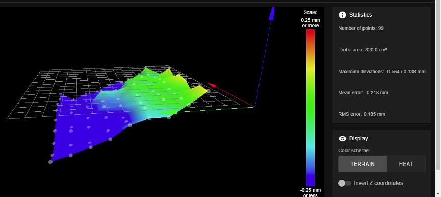
That height map is pretty bumpy.
What sort of build surface or system are you using?
You might want to change your M557 command by replacing the S20 with P20.
That will give you a denser grid better able to cope with a bumpy build surface.
And create your height map with the bed at temp - if you aren't already doing that.
Frederick
-
What sort of build surface or system are you using?
i have a E3D Big Box printer that sat in my boss office for the past 6 years. it has a black bed with a piece of glass on top for the build surface. the bed is original to the printer. We use hair spray to help the print stick. It is a vary smooth surface but the bed does have a hump in the middle compared to the bed sides.
You might want to change your M557 command by replacing the S20 with P20.
That will give you a denser grid better able to cope with a bumpy build surface.
ok i will make this change.
And create your height map with the bed at temp - if you aren't already doing that.
the bed and hot end both are on for that procedure.
ok send a new map when done. thanks
-
@phaedrux said in Printing problem with filament or set up?:
For the probe, what kind is it? IR probe? If so glass can be a bit problematic because it's transparent to IR so would need to be able to detect the actual bed surface. When you add hair spray etc to the bed it can block the IR and you can end up with a patchy heightmap. What does your heightmap look like now? Post a photo. You could also try placing a piece of plain white paper on the bed and probing on that to compare.
So seeing your heightmap and your description of the bed I think you may be experiencing what I described. Assuming it's an IR probe.
Have you tried doing a mesh with plain paper on the bed yet?
The first layer looks under extruded and the rest of the layers look over extruded, so I think you are printing the first layer too high and your flow rate is also too high.
Fixing the probe mesh with a piece of paper should help get your first layer distance better.
If you've already calibrated the steps per mm for the extruder you can probably reduce the flow rate in the slicer from 100% to 90 or 95%
-
at this point i am trying to get a better a level on bed by using the metal standoffs for small adjustments and getting the four corners of the bed to the same height and then yes the paper on the bed and run mesh compensation again.
for right now the mech map is looking somewhat better. i no longer have red.

so if i can do a better job leveling the bed maybe this issue will go away with the mech compensation. so more level bed and paper on bed to run mech compensation and i hope this issue goes away.
you have stated:
The first layer looks under extruded and the rest of the layers look over extruded, so I think you are printing the first layer too high and your flow rate is also too high.
At this point the first layer has the lines touching and not separated. But when i run the cube base, just the first layer only i can see where first layer gets thin where the nozzle is too close and then i see where the extruded lines are perfect little lines and not touching and the nozzle is too far away from the bed. So this is what i am trying to over come so i can get a perfect first layer which is even.
Fixing the probe mesh with a piece of paper should help get your first layer distance better.
yes i am hopping so. doing this today.
If you've already calibrated the steps per mm for the extruder you can probably reduce the flow rate in the slicer from 100% to 90 or 95%
yes i have calibrated mm per step but since then i have cut that number in half in the software and this is what i am getting at this point. so after i get the first layer to go down flat thin i will let the print run to do the 2 layers for the base and i am hopping there is no more sand waves on those layers.
i am having some trouble of finding where i need to change some of these settings in the software. Like flow rate you have mentioned above in the slicer for flow rate? i will to find that. i am figuring out with your guys help on what to change but where to change it in slicer or software and what setting to do it under.
that is where we are at this morning.
-
@testpro
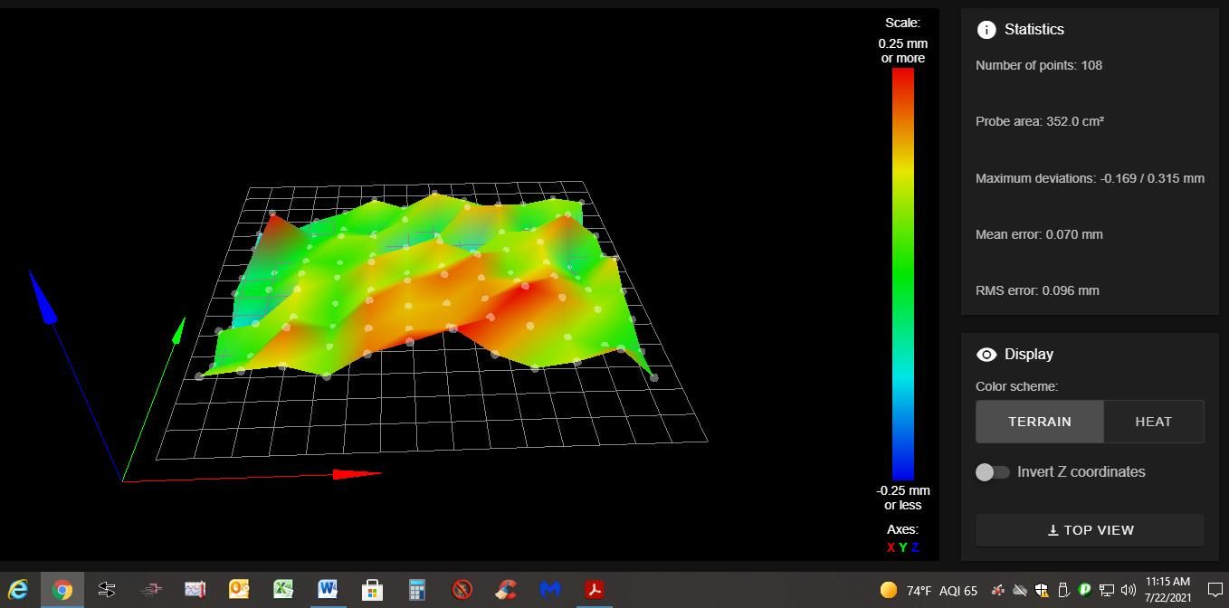
ok leveled the bed to the point where all four corners of the bed are within .2 MM.the height map with paper on bed:

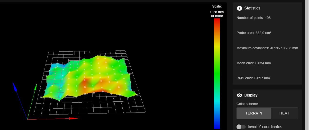
Next i put tape on the bed and performed another height map:

note this one has neg reading of -0.196 too 0.233 mm for a 0.429 mm
so the compensation needs to travel 0.429 mm in total for compensation. But the point to point is really not that much. so now i print the base layer and in some places you can see where it is to thin. so still not keeping up. so either the compensation is not working fast enough or the probe is giving bad measurements.
so now going to run the first layer base twice in a row with no changes and if they look different then the probe is bad.
also as a side note the heat map on the bed is not even either. this can be some of the problem?
-
You can test if the probe is reading correctly:
- move the probe to the center of the bed.
- execute a G30
- move the nozzle to the center of the bed
- jog down until the nozzle is just touching the bed
- verify the position reported is Z=0
I find it easier to move to Z=1 and then use a 1mm thickness gauge to verify the gap.
Also remember you need to execute a single G30 at some fixed XY location to set the Z=0 datum before issuing the G29 to create the height map.
Some folks suggest picking the fixed XY location from one of the G29 probe points.
I just use the center of the bed.
Frederick
-
@fcwilt
ok but my probe is positioned behind my duel hot ends in the center. so when my hot ends move together so does my Z probe. so if i move my hot end and Z probe to center of board and then make the nozzle touch the bed and then do a G30 command this will make Z=0 and now if i home all then move it back to the same position and have it touch the bed it should be Z=0? or is it simple as making Z=0 with nozzle on bed then lower Bed 50 mm and then move it back 50 MM then Z=0 if not i am getting different readings. -
When using G30 to set the Z=0 datum the Z Trigger Height setting in the G31 command is the key.
If that value is off then setting the Z=0 datum will not work as desired.
In theory after setting the Z=0 datum at some XY location using G30 then, with the nozzle at the same XY location, a G1 Z0 should result in the nozzle just touching the bed.
I am just suggesting you verify if that is true, using the steps I listed.
Frederick
-
@fcwilt
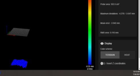
ok at this point i am calling this a loss.i have adjusted the Z probe to be 1 mm higher than the extruder nozzle. and ran a new height map and here is what I got.

this makes no sense to me. so i ran two more height maps and now they like the old Hight maps.
i readjusted the z = 0 point and i get a neg. number and i put that in and cycle power and reset software twice.
ran new height map and it looks like the old one except i am within 0.3 mm across the bed. go to print base of the curve file and the nozzle 1/2" off the bed so we readjusted the z =0 again and the same thing happens. so then i changed the neg. number to positive number and go to print and the nozzle is being pushed into the bed.
it seems i am getting consistent numbers then out of now where everything changes. so guess there is something wrong with the probe.
So BL Touch is all i am hearing about so will it work with the board board (Duet 2 wifi) or is there something else i need to do.
it is either this or i just throw the printer away. very frustrating.
-
-
https://duet3d.dozuki.com/Wiki/Test_and_calibrate_the_Z_probe
Are you following the instructions here for setting the G31 Z trigger offset?
A BLtouch is a good option if your bed surface doesn't work well with an IR probe, which perhaps yours does not. Though it does have it's own set of demands to work well. Because it's a retractable probe, it requires a bit more wiring and configuration.
-
the link you have is what i have been following this whole time calibrate the Z probe. i can not get a consistent result when repeating the read out. two or three times it reads one thing and then it just goes and comes back with something totally different. From project to project and from day to day i have go back over things and reset them because it will not do what is supposed to.
if anyone have a better idea i am all ears because right now it is not consistent. i am getting tired chasing the same issue around.
so what other options are there?
-
The main variable for the IR probe is the IR reflection of the bed surface. So if you've tried with a plain piece of paper on top of the glass and it's still highly inconsistent than it's possible the probe itself is damaged/failing/dirty.
Can you post a photo of your probe and print head?
-
@phaedrux
yes i have done the paper on the top taped down and get the same result of a very lumpy height map. the sensor has been cleaned as well. Several times.i am thinking this is so frustrating because it reads rights a few times then goes and does something else for readings. the reading are consistent only for 3 to 4 times thin it changes .
i would like not to put more money into this project but if the Z is not consistent, i do not have a choice.
the one with the blue cover is E0, E1 is not being used at this time and nozzle is removed.

-
You'd have to take the probe out to get a good look at it, but it seems well protected there.
If you don't want to get another probe you could try manual probing instead. It's a bit time consuming, because it's a totally manual process, but it would let you get good accuracy to confirm that things are otherwise working during a print.
to set manual probing.
M558 P0 H4 F200 T6000
G31 X0 Y0 Z0 P500
M557 set whatever your current grid range is, but change to P3 to create a 3 by 3 grid just to reduce the number of points you have to probe.Now when you do a G28 or G29 when it gets to requiring a G30 to probe the bed you will be prompted to jog the nozzle down manually.
-
@testpro
ok so i put the above code in one line at a time and the M557 will set the grid.
so when the extruder moves to a location it will let me know to lower the nozzle until it cripsa sheet of paper and then it ok or whatever it will state and it will move to next point and do it again?if this what you are saying.
-
Yes that's the gist of it.
Test it first with a single G30. It should pop up a dialogue box to let you jog Z.
-
ok done a manual bed leveling. but now how do i turn this off.
the thing will not home on z i have to adjust it.
-
I'm not sure what you mean. The idea is that manual probing replaces the probe calls when you don't trust the probe. To turn it off you would change the configuration back to your other probe I suppose, but then if you use that to home and it doesn't give a good result your Z0 would be off and you're back to square one.