Running old AC drive spindle with frequency inverter
-
I am retrofitting old manual milling machine with frequency inverter and I will need 2 diferent rpm speeds with reverse (drill and tap combo tool) Duet wifi with breakout board.
The inverter I got is this
ELDI
I will use digital inputs 24 V on the inverter
1- ON
2- Forward/backward
3. Fixed speed 1
4. Fixed speed 2
My P0 and P1 outputs are occupied for 2 solenoids for clamping of the part
I plan to use P2 for ON/Off of the inverter
Wich outputs you will suggest for the other 3 24V outputs?
Maybe fans ? -
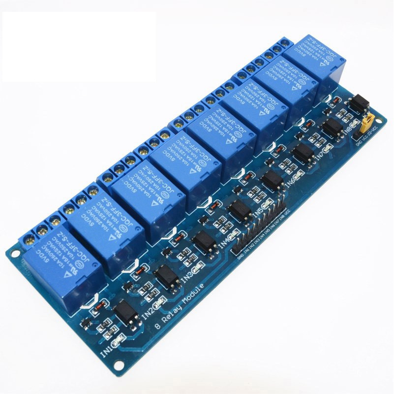
@martin7404 I strongly recommend that you use opto isolators to interface the Duet to the spindle controller. Figure 4.1. shows switches connected between +24V from the controller and the various inputs. This switches can be the output sides of opto isolators, observing correct polarity. The inputs of the opto isolators can be driven from whatever spare outputs on the Duet you have, with series resistors appropriate to the voltage. If that system already has a DueX or expansion breakout board than you could use the 5V PWM outputs from those boards.
You can buy opto isolator boards, for example https://www.amazon.co.uk/Optocoupler-Isolation-Module-8-Channel-Converter/dp/B08LVXX6MV (note, I haven't used this board so this is not a recommendation).
-
@dc42 will this work ?
I have it locally

-
@martin7404 yes that should work, if none of the spindle controller inputs needs a PWM signal.
-
@dc42 So then 2 PWM output on expansion board and 2 fan outputs to this board
I will make a makro for M3 M4 M5 and SS1 and SS2 for the speed seting -
@martin7404 it looks like that relay board has a common ground input, in which case you can't use a mixture of fan outputs and 5V outputs to drive it.
-
@dc42 thank you I ended up using this board for 2 signals ON and Reverse, and PWM to ananalog board for the RPM