change the acceleration and deceleration settings that M567 uses
-
Re: creating seemingly instant extruder change
I've posted on this topic before but the forum suggested starting a new post.
I'm trying to get two extruders to do a controlled handover without interruption in printer head movement.
As a reply to my previous post M567 was suggested and I have managed to get this working with a workaround but I'm looking for a cleaner solution to future proof my machine.
A handover with M567 looks like this:
M567 P0 E1.0:0.0
G1 X150 Y0 E150 F6000
M567 P0 E0.0:1.0
G1 X150 Y0 E150 F6000
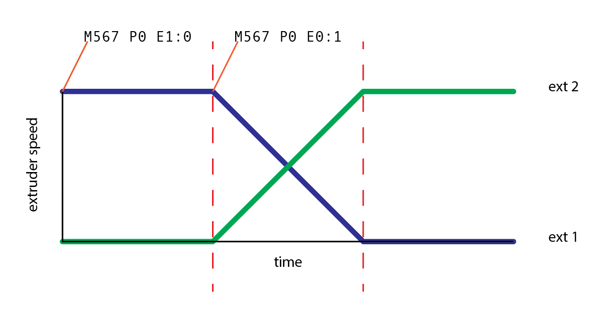
I expected the motor speeds to be altered like the diagram below, which would result in no need for the X speed to change because the same amount of material would be extruded at all times:

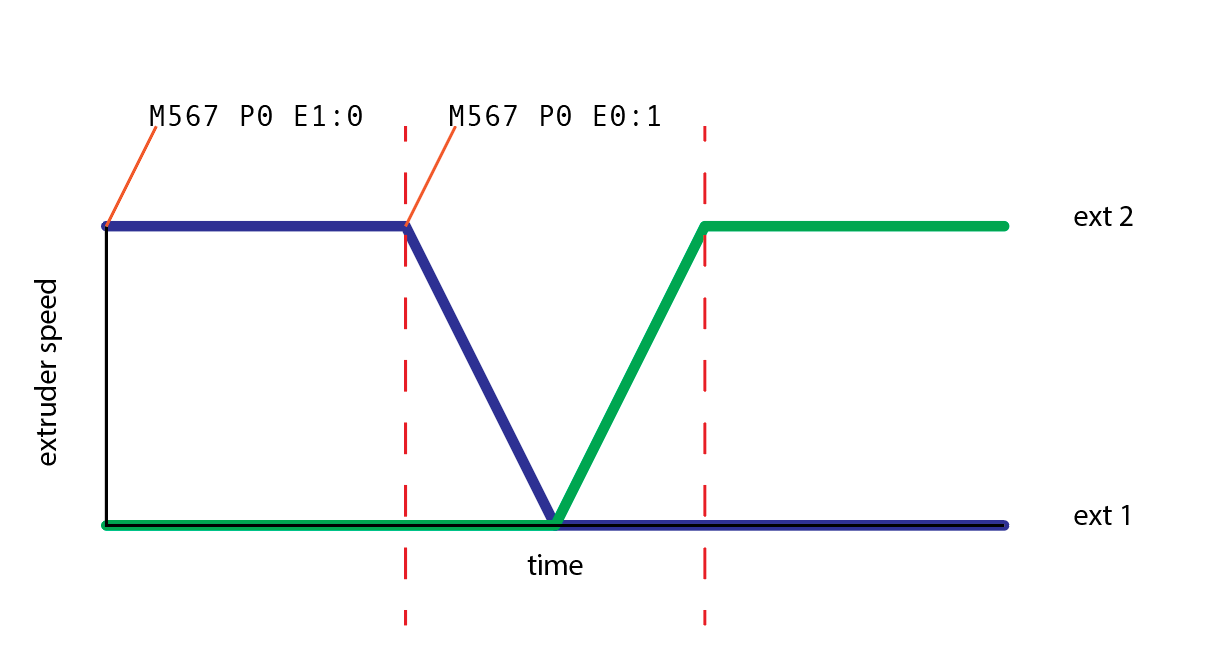
However the actual result looks like this which results in the X motion having to come to a stand still to make sure the same materials is extruded during its movement.

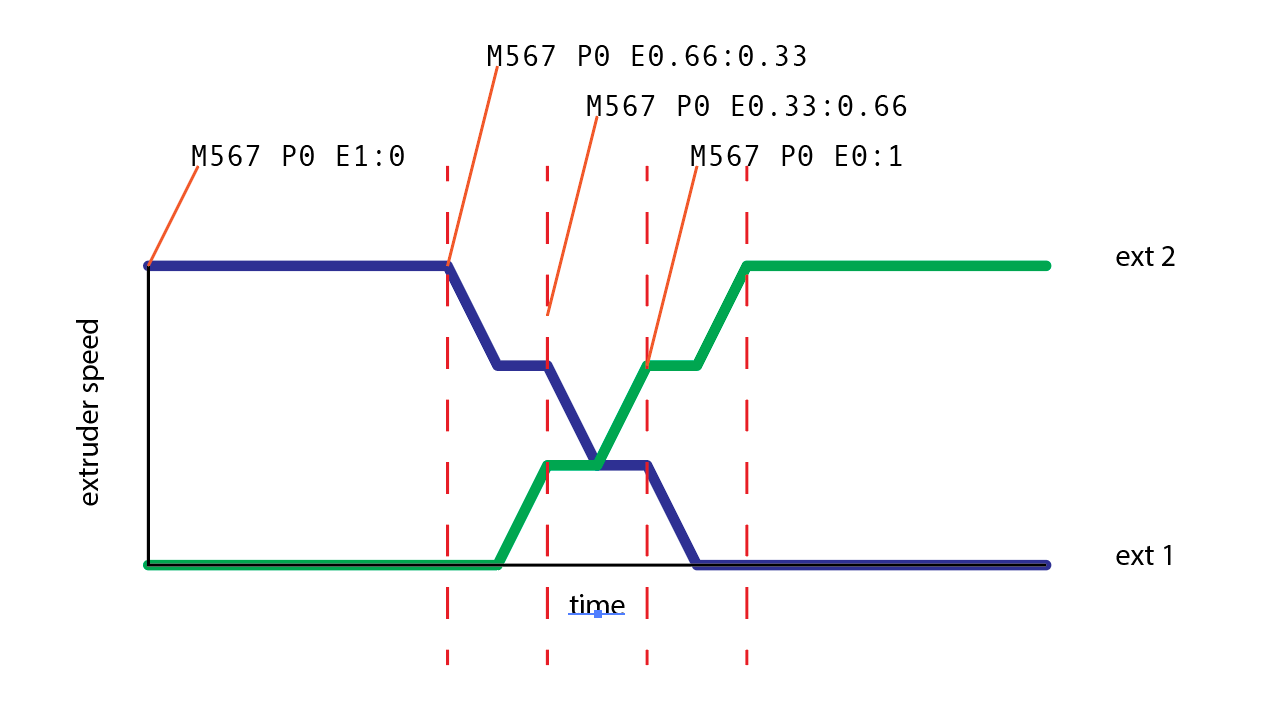
The most obvious and impossible workaround would be instant speed change which doesn't work in the real world for obvious reasons. The workaround I could come up with which does work is controlling the handover by dividing the handover in multiple smaller steps like the example below.

In order for this to work the instantaneous speed change has to be double as high as required because it goes through multiple phases of accelerating and maintaining speed instead of one fluent speed change. My machine has to run at 100mm/s and the change has to happen over 25mm which means that with 10 steps it requires a 1200 mm/s instantaneous speed change.
I'm pretty sure I can make this work the way it is but I have a feeling I'll be making my goals barely while speed change according to the first example would make things work far better as well as be easier. In my previous builds with external PCB's for extruder control the handover happens over much shorter distances which allowed higher print speeds etc.
My question is if there is any way of altering the way the firmware handles the acceleration and deceleration of the extruders. If I could somehow change the behaviour to my first diagram instead of the second my results would greatly improve and the software that generates my Gcode could be written with far less clutter and be much more resilient to any future changes. It would also limit me far less in the further development of this project.
I'm open to any solution and all help is welcome, I'm just hoping to do this in a less "hacky" way to make fixing inevitable issues easier for future me.
-
@GillesDB Not sure I fully understand but if you want the X axis to run at a constant speed of 100mm/sec (6,000 mm/min) then you'd need to set the instantaneous speed change to be at least 100mm/sec (6,000 mm/sec). Then there won't be any acceleration or deceleration phases. But because extruders are treated like axes in G1 moves, and all axes have to start and end their move at the same time, then the extruder must have equally high or higher instantaneous speed change. You can set it as high as you like but not lower, otherwise the extruder move timing will dictate the X axis timing resulting in a reduction of X axis speed.
As for changing between extruders, AFAIK G1 moves are carried out sequentially. The first must end before the second can start. That being the case then the only way you can simulate a progressive change in mixing ratio, is to use small segmented moves. The smoothest would be in 1% steps so you could segment that 150mm move into 1.5mm segments with a change in mixing ratio at each move boundary. i.e M567 P0 E1.00:0.00, G1 X1.5 E1.5 F6000, M567 P0 E0.99:0.01, G1 X1.5 E1.5 (the feed rate will be maintained so you don't have to specify it again, nor do you have to specify a "Y" values if there is no Y movement), M567 P0 E0.98:0.02, G1 X1.5 E1.5, etc.....A good text editor or other script would be the best way to generate that section of gcode.
In theory, that should generate a smooth transition between one extruder and the next over the course of 150mm in X without any change in speed (providing you set the jerk value high enough). As with all other gcode commands, you can have M566 embedded in the gcode at the start and end of that sequence if you need to use lower jerk elsewhere.