• Tags
  • Documentation
  • Order
  • Register
  • Login
Duet3D Logo Duet3D
  • Tags
  • Documentation
  • Order
  • Register
  • Login

Filament monitor using HC-020K encoder

Scheduled Pinned Locked Moved
Filament Monitor
5
51
7.7k
Loading More Posts
  • Oldest to Newest
  • Newest to Oldest
  • Most Votes
Reply
  • Reply as topic
Log in to reply
This topic has been deleted. Only users with topic management privileges can see it.
  • undefined
    paboman
    last edited by 18 Mar 2018, 14:06

    EUREKA!
    adding 45k (15x3) resistor between pin 1 and 3 of LM393 solved the issue

    [c]Pulse-type filament monitor on endstop input 3, enabled, sensitivity 1.89mm/pulse, allowed movement 70% to 130%, check every 10.0mm, current position 0.0, measured sensitivity 1.88mm/pulse, measured minimum 100%, maximum 101% over 373.1mm
    [/c]

    holding the extruder wheel from turning trigger the pause as it should

    now the last question is: why the sensitivity calculated is 1.89 instead of the 4.1 that mathematical model gives us ?

    thank you David!

    1 Reply Last reply Reply Quote 0
    • undefined
      dc42 administrators
      last edited by 18 Mar 2018, 14:34

      Perhaps your extruder steps/mm is wrong? Please explain how you arrived at 1166. From your video, I think you don't have an extruder connected to the extruder drive yet, only the encoder wheel - is that correct?

      I guess it's also possible that you are still getting more than one edge at each transition. If that's the case, reducing the value of the resistor will help, for example try 15K. If you make the value too low then it won't produce any pulses at all. However, as your variation during calibrarion seems to be very low now, that's probably not the cause.

      Duet WiFi hardware designer and firmware engineer
      Please do not ask me for Duet support via PM or email, use the forum
      http://www.escher3d.com, https://miscsolutions.wordpress.com

      1 Reply Last reply Reply Quote 0
      • undefined
        paboman
        last edited by 18 Mar 2018, 15:49

        The motor have 200 full steps per revolution (1.8 deg per full step)
        The gear ratio is 1:13.76 so the number of full step per revolution is 13.76 x 200=2752 full steps
        The hobbed gear diameter is 12mm so the Circumference is 3.14 x 12=37.68mm
        with full step than the steps/mm is 2752/37.68=73.03 step/mm
        Driver works at 1/16 step so 16x73.03=1168 steps/mm

        The extruder motor is connected to E0 but instead of the hobbed gear i mounted the encoder wheel (only for testing)

        1 Reply Last reply Reply Quote 0
        • undefined
          dc42 administrators
          last edited by 18 Mar 2018, 17:02

          So instead of a 12mm diameter hobbed gear you have a 26mm extruder wheel. So the amount of extruded filament will be 12/26 of the amount you have assumed in the encoder wheel calculations. (12/26) * 4.1 = 1.89.

          Duet WiFi hardware designer and firmware engineer
          Please do not ask me for Duet support via PM or email, use the forum
          http://www.escher3d.com, https://miscsolutions.wordpress.com

          1 Reply Last reply Reply Quote 0
          • undefined
            paboman
            last edited by 18 Mar 2018, 20:30

            That is right! Definitely something I have overlooked.
            thanks again

            1 Reply Last reply Reply Quote 0
            • undefined
              Monster Delta
              last edited by 11 May 2018, 10:21

              Does the resistor go between A0 and GND OR VCC AND D0?

              undefined 1 Reply Last reply 11 May 2018, 10:40 Reply Quote 0
              • undefined
                dc42 administrators @Monster Delta
                last edited by 11 May 2018, 10:40

                @monster-delta said in Filament monitor using HC-020K encoder:

                Does the resistor go between A0 and GND OR VCC AND D0?

                Which resistor are you referring to? If you mean the one to clean up the output of the encoder, it's neither, it's between pins 1 and 3 of the LM393 chip.

                Duet WiFi hardware designer and firmware engineer
                Please do not ask me for Duet support via PM or email, use the forum
                http://www.escher3d.com, https://miscsolutions.wordpress.com

                undefined 1 Reply Last reply 11 May 2018, 10:44 Reply Quote 0
                • undefined
                  Monster Delta @dc42
                  last edited by 11 May 2018, 10:44

                  @dc42 thank you for clearing that up

                  1 Reply Last reply Reply Quote 0
                  • undefined
                    paboman
                    last edited by paboman 12 Jun 2018, 11:48

                    @dc42
                    I am now printing as the printer is ready and sometimes I get error:

                    Extruder 0 reports too much movement
                    
                    M591 D0
                    Pulse-type filament monitor on endstop input 3, enabled, sensitivity 1.89mm/pulse, allowed movement 60% to 300%, check every 10.0mm, current position 0.0, measured sensitivity 1.785mm/pulse, measured minimum 99%, maximum 160% over 4127.0mm
                    

                    I changed the sensitivity with no luck

                    M591 D0
                    Pulse-type filament monitor on endstop input 3, enabled, sensitivity 1.78mm/pulse, allowed movement 60% to 300%, check every 10.0mm, current position 0.0, measured sensitivity 1.799mm/pulse, measured minimum 90%, maximum 218% over 5322.7mm
                    

                    then when it stops it says maximum was 676%, why ?

                    M591 D0
                    Pulse-type filament monitor on endstop input 3, enabled, sensitivity 1.81mm/pulse, allowed movement 60% to 300%, check every 10.0mm, current position 0.0, measured sensitivity 1.820mm/pulse, measured minimum 90%, maximum 676% over 8980.6mm
                    

                    I increassed the sensitivity to 300% hoping for a workaround solution but still getting the error after many hours.
                    This is not happening if i print in vase mode

                    undefined 1 Reply Last reply 14 Jun 2018, 16:29 Reply Quote 0
                    • undefined
                      paboman @paboman
                      last edited by 14 Jun 2018, 16:29

                      @dc42
                      David, can you take a look at this please?

                      1 Reply Last reply Reply Quote 0
                      • undefined
                        dc42 administrators
                        last edited by 15 Jun 2018, 21:50

                        Did you add the resistor to your HC-020K board to get rid of the noise on the output?

                        Duet WiFi hardware designer and firmware engineer
                        Please do not ask me for Duet support via PM or email, use the forum
                        http://www.escher3d.com, https://miscsolutions.wordpress.com

                        undefined 1 Reply Last reply 16 Jun 2018, 17:13 Reply Quote 0
                        • undefined
                          paboman @dc42
                          last edited by 16 Jun 2018, 17:13

                          @dc42
                          sure, that was the first thing you have figured out.

                          1 Reply Last reply Reply Quote 0
                          • undefined
                            dc42 administrators
                            last edited by 16 Jun 2018, 17:28

                            It could mean that you are still getting noise on the output sometimes. In particular, if the extruder stops with the wheel just on the boundary of blocking/not blocking the light to the opto sensor, there could be noise at that point caused by vibration. You could try reducing the value of the resistor. 10K or lower will stop the sensor working completely, but 15K to 30K might work.

                            Duet WiFi hardware designer and firmware engineer
                            Please do not ask me for Duet support via PM or email, use the forum
                            http://www.escher3d.com, https://miscsolutions.wordpress.com

                            1 Reply Last reply Reply Quote 0
                            • undefined
                              paboman
                              last edited by 26 Nov 2018, 21:07

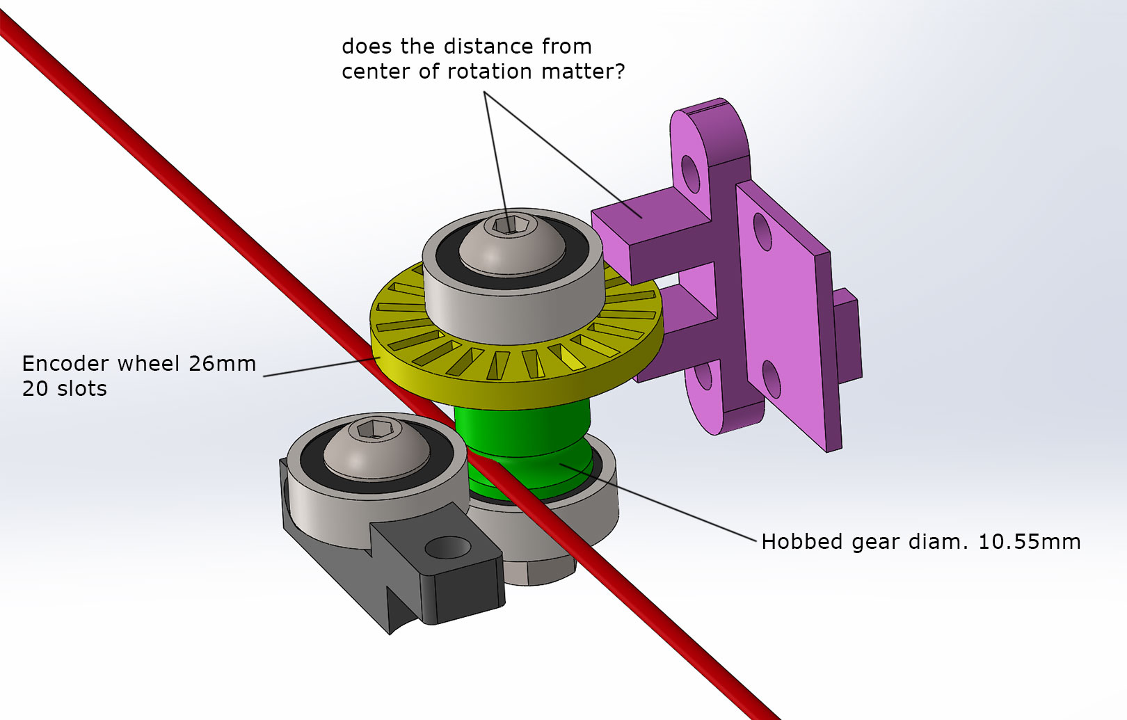
                              I changed the filament monitor design and before ordering other resistors (with different values) I want to be sure my calculations are right, maybe this time the filament monitor will work just fine with the 45K ohm resistor.

                              0_1543266068137_filament-monitor.jpg

                              The filament runs on a hobbed gear of 10.55mm in diameter = 33,14 mm in circumference
                              33,14mm of extruded filament gives 20 pulses
                              33,14/20 = 1,657 mm/pulse

                              @dc42 can you confirm this please?

                              Can the distance from the center of rotation of the sensor affect the reading ?

                              thanks!

                              Tony Owensundefined 1 Reply Last reply 10 Jan 2020, 14:37 Reply Quote 0
                              • undefined
                                dc42 administrators
                                last edited by 27 Nov 2018, 10:17

                                That calculation sounds right.

                                The distance you refer to will affect how clean the output of the opto switch is. If you use a suitable feedback resistor in the comparator circuit then it shouldn't be too critical, because the comparator will clean up the output.

                                Duet WiFi hardware designer and firmware engineer
                                Please do not ask me for Duet support via PM or email, use the forum
                                http://www.escher3d.com, https://miscsolutions.wordpress.com

                                1 Reply Last reply Reply Quote 0
                                • create0undefined
                                  create0
                                  last edited by 21 Jul 2019, 20:26

                                  Thank you so much for the indeed, incredible concept to share with. I do admire the effort and will continue to learn from these forums.

                                  1 Reply Last reply Reply Quote 0
                                  • Tony Owensundefined
                                    Tony Owens @paboman
                                    last edited by 10 Jan 2020, 14:37

                                    Hi @paboman

                                    I'm interested to know how this slotted optoswitch worked out for you as a basic filament sensor? Did you complete your development? Did you encounter any problems you could not solve?

                                    cheers

                                    undefined 1 Reply Last reply 11 Jan 2020, 16:08 Reply Quote 0
                                    • undefined
                                      paboman @Tony Owens
                                      last edited by 11 Jan 2020, 16:08

                                      @Tony-Owens
                                      is working quite well, I would like to reduce the dimension of the assembly in the future.

                                      1 Reply Last reply Reply Quote 0
                                      • First post
                                        Last post
                                      Unless otherwise noted, all forum content is licensed under CC-BY-SA