Mesh bed leveling (3/4 of the bed works flawlessly)
-
I would be tempted to take it back a few steps just to ensure all is fine with your limits and probe offset. I find it easier working with (0,0) being the centre of the bed, but that's personal preference. If you do this M208 has been tidied up so you can do maximum and minimum on one line like:
M208 X[min]:[max] Y[min]:[max] Z[min]:[max]
-
Alright, I fixed the mesh grid, and will retry with the print that's giving me trouble. I measured the distance from 0,0 to the probe, and it was as you said. I also preferred it when the printer homed in the middle, but was unsure of how to do that. I'm guessing its a tick box I missed somewhere, I'll take a look. Although, I wasn't too sure how the mesh leveling worked on my other board, I just knew it worked and all was well lol.
Alright, The test print started, but the results are pretty much identical. I'm starting to think its the location of the sensor, but I have no evidence to support that theory. I might have to design a different mount, that would be closer to the nozzle.
-
looks like my bed is horribly out of level, I'll fix that now, but it shouldn't matter? my Anet board never really cared lol
-
Twist may give you a bit of an issue because of the large y offset. I'll reply later this evening about (0,0) in the centre.
-
Alright. Looks like I need some anti-backlash for my Z-axis, as it was a good centimeter off. I'm re-leveling now and will try again.
Edit: Alright, after levelling my bed, everything seems to be working better. Probem is, I just snapped off my bl touch holder. I'll have to super glue it and print a new one. I'm still interested in the centre homing spot though
") Thanks for all the help!
Thanks for all the help! -
Morning!
Later (or earlier, depending on perspective!) than I had anticipated. Glad you're making progress. I'm having bed levelling issues myself and am part way through a thorough test on an inductive probe.
- Measure the size of your printable area in x and y axis. If new to the machine double check which is x and y by nudging the axis on duet web control. You want to measure parrallel (in the same direction as) the motion of the axis. I always assume the x axis is left to right as you are looking at a machine and came unstuck many times with my cantilever Ormerods in the simplest view the designers took a leg of the z axis and rotated the whole machine -90 degrees about z!
")
For my machines with MK3 alloy beds this is about 214mm. From your config file I'm assuming your bed is 215 in x and 200 in y.
- Measure the travel from the home positions to the the x and y axis to the closest part of the bed.
Again assuming (0,0) places the nozzle directly over the minimum corner of the printable area then you machine needs to travel 30mm in x, and 43 in y.
- Adjust M208 to suit the numbers you have recorded.
You had the following in your config:
M208 X-30 Y-43 Z0 S1 ; Set axis minima
M208 X215 Y200 Z240 S0 ; Set axis maximaThis is the same as:
M208 X-30:215 Y-43:200 Z0:240; Set axis limits
The distance from the central point of the printable area to the X limit switch is:
-(215/2) - 30 = -107.5 - 30 = -137.5
The distance from the central point of the printable area to the edge of the printable area furthest from the X limit switch is:
215/2 = 107.5
The distance from the central point of the printable area to the Y limit switch is:
-(200/2) - 43 = -100 - 43 = -143
The distance from the central point of the printable area to the edge of the printable area furthest from the Y limit switch is:
200/2 = 100.00
This would make your M208 look like:
M208 X-137.5:107.5 Y-143:100 Z0:240; Set axis limits
- Just as a sanity check, check the distance between the minimum and maximum positions in each axis to ensure they haven't changed:
X Axis:
Old == New
215 - -30 == 107.5 - -137.5
245 == 245Y Axis:
Old == New
200 - -43 == 100 - -143
243 == 243That should sort you out. I'll add a bit more about fiddling these settings to make it more accurate another time. Make sure you change your slicer too!

- Measure the size of your printable area in x and y axis. If new to the machine double check which is x and y by nudging the axis on duet web control. You want to measure parrallel (in the same direction as) the motion of the axis. I always assume the x axis is left to right as you are looking at a machine and came unstuck many times with my cantilever Ormerods in the simplest view the designers took a leg of the z axis and rotated the whole machine -90 degrees about z!
-
Morning! Albeit a little early as it's 2:00 am here haha.
I plugged the new M208 numbers in, and when instructed the nozzle finds (0,0) in the middle of the bed which is awesome! My bed is technically 220x220, but I'm having issues with the X-carriage and my Y-axis decreased in size when I upgraded my frame sadly. when I fix my x-carriage issues, I'll follow your math to get the true center (which is only 2.5mm away anyways).
I do see an issue with where my BL touch is probing. it doesnt really probe in the centre. More like towards the front right. Then when I try to level it its starts very far back, and eventually runs off the bed.
I'm still using the mesh grid from earlier, I'm guessing that's the issue?
I'm trying to figure it out now.
-
Yes you would need to do a new mesh. Out and about now but if I've signal while the little one is asleep I'll have a look at the mesh.
Regards the BL touch some people have reported that they needed to disable the heater for the duration of the probing and they have also reported issues with probing directly over magnets in a magnetic bed.
-
Sounds good
I've got lots of time. I designed a new BL touch holder. Ill try to print it quickly, and see if it works. If it does, it would allow me to probe my whole bed, aswell as more z height and maybe even a bit on the X axis. I'll update in a bit. (If I don't pass out again, but I should be good for another while here lol.) -
Okay, So i made my BL touch mount, and it came out perfect the first time! even the quality was top notch due to the leveling lol. I measured the distance from the nozzle, and it is 3mm to the left on the x-axis, and 33mm behind it. I'm pretty happy with how it turned out as the carriage is much cleaner looking. I think I might be done for the day though as it's 4:35am now. Time for a cigarette, and to head off to bed. I'll have to figure out the z offset tomorrow as well for what feels like the thousandth time. Oh well. Its all worth it when it all works reliably in the end. After that, you take it apart again and make it better lol.
Have a good day!
-
Working on the other side of my day here! It was about that for my first post but no sign of my son falling asleep yet!
-
@doctrucker Hehe fair enough
Yeah, I'm all the way in Canada, how about you?I think I was successful in gaining an extra 5mm on my X gantry, which means it's working area can be set to it's original 220mm. I'll have to change the axis limits first, and then I'll try working on the mesh grid, which should now be 220X210.
I like how you can put these codes into the custom section of the configurator. It makes editing the other code much easier.
-
I'm in the UK.
So from your comments earlier if you moved your nozzle to (0,0) over a piece of paper and marked the location of the probe you would have to move the nozzle to (-3,33) to be over that point? If so that would make your G31 line in your config (although you're liekly to need to fiddle the z trigger point):
G31 P500 X-3 Y33 Z0.75
This would mean based on:
M208 X-137.5:107.5 Y-143:100 Z0:240; Set axis limits
You can probe the following points area:
X Axis -140.5 to 104.5
Y Axis -110 to 133As discussed earlier the printable area is:
X Axis -107.5 to 107.5
Y Axis -100 to 100So the area we can probe (with 5mm 'spare') is:
X Axis -102.5 to 99.5
Y Axis -95 to 95Your mesh config line becomes:
M557 X-102.5:99.5 Y-95:95 S40.4:38 ; Define mesh grid
The S part of the above sets the grid size, and the above creates an array of 25 probe points.
Use the gcode reference as a guide when learning about the config file. I've added links to the config lines above to help explain them. Test my suggested config lines carefully and hover over the emergency stop on Duet Web control the first time you use it as I'm not always right myself on these things first stab!
-
You'll need to work on the above a little. Your config maximum limits should be set to avoid physical collisions on the machine rather than making sure the nozzle doesn't go outside the printable area. carefully move the axis to the software limit, making sure it doesn't his a physical limit first. If it hits a physical limit fist you need to reduce the respective axis travel to ensure it doesn't hit that physical limit. If it doesn't hit a physical limit and there is room to spare then increase the limit and carefully try again until you have the software limit ~2mm before the physical.
With the maximum limits of travel properly set up you should be able to adjust the mesh config and get a little more bed area probed.
-
Here are the new limits I just found, and the mesh I was working on, but was not totally correct. I'll try to fix my code now.
M208 X-140:113 Y-143:100 Z0:240; Set axis limits
M557 X-105:105 Y-100:100 S52.5:50 ; Define mesh gridThanks
I'll update once I know more.
Update: Alright, everything seems to be working pretty well with the grid you sent over
I'll have to fiddle around with it a tiny bit to get the Y axis probed a tiny bit farther back, but otherwise it's probably the best bed leveling I've ever seen on my printer. Thank you! I'll take a look at the links above, and as an electronics student I mostly understand the coding aspect, Its just the math that gets me (And maybe some of the coding without realizing it haha).Thanks again
-
I guess I have another question, why is the probe homing at some place to the right/front of the bed? is there another command to set the probe home position?
I also realized why the probe doesn't probe all the way to the back. It's because the nozzle itself can't reach all the way back there, so its out of the axis limits. At least that's what I think.
Everything is working pretty well now, Just gotta adjust some things in my slicer. Thank you!!!
-
@gtaman said in Mesh bed leveling (3/4 of the bed works flawlessly):
I guess I have another question, why is the probe homing at some place to the right/front of the bed? is there another command to set the probe home position?
Homing of the z axis is controlled by two things, homeall.g and homez.g. You can home the z axis individually or have it home as a set in home all. With my cartesian machines I tend to set the contents of homeall.g to refer to the other homing macros rather than write the detail out in two places. Yes there are some tricks to save a little time (particually with core XY) but to be honest I find it begging for mistakes having the two scripts do different things. My home all looks like:
; homeall.g
; called to home all axes
;
m98 Phomey.g
m98 Phomex.g
m98 Phomez.g@gtaman said in Mesh bed leveling (3/4 of the bed works flawlessly):
Everything is working pretty well now, Just gotta adjust some things in my slicer. Thank you!!!
Good to hear, no problem. Spent many an hour chasing an extra few mm on the probed bed area myself! Currently wrestling a large offset needed to put an 18mm body inductive sensor between the smooth rods and nozzle on a P3Steel machine!
-
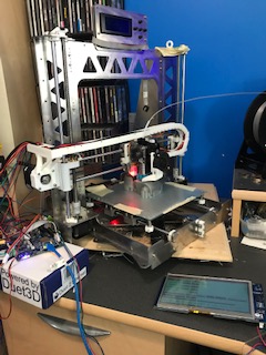
Hey! That looks pretty similar to my printer. Mine is the Tatara Hayabusa from thingiverse. I had protocase make it for me since I had a discount for being a student
I had to relocate my BL touch to the same location you're talking about. I originally started off with the Anet A8, and slowly upgraded everything. the only things left are the stepper motors, rods, and endstops.I was thinking of getting these, but I'm not sure if they'll work with the duet as I think you'll need removable stepper drivers.
https://spool3d.ca/mks-base-servo42-closed-loop-stepper-motor/
Maybe the duet has it built in? or maybe I just need stronger motors. I'll probably just start a new thread about it
Thanks one last time, I wouldn't have got it done over the weekend if it wasn't for your help lol