Duet3D Logo Duet3D
    • Tags
    • Documentation
    • Order
    • Register
    • Login

    Mesh calibration not working or what am I doing wrong?

    Scheduled Pinned Locked Moved Unsolved
    Tuning and tweaking
    11
    93
    5.2k
    Loading More Posts
    • Oldest to Newest
    • Newest to Oldest
    • Most Votes
    Reply
    • Reply as topic
    Log in to reply
    This topic has been deleted. Only users with topic management privileges can see it.
    • Vetiundefined
      Veti
      last edited by

      @Dep said in Mesh calibration not working or what am I doing wrong?:

      your probe is to the right and behind the nozzle?

      1 Reply Last reply Reply Quote 0
      • Depundefined
        Dep
        last edited by

        No. Probe is to the left and behind the nozzle. (Homing point on the left and front of the printer)

        1 Reply Last reply Reply Quote 0
        • Depundefined
          Dep
          last edited by

          2019-10-25_21-13-15.png

          1 Reply Last reply Reply Quote 0
          • Vetiundefined
            Veti
            last edited by Veti

            G31 P25 X27 Y-4 Z1.78 ; set probe height

            your configuration says to the right and infront.

            1 Reply Last reply Reply Quote 0
            • Depundefined
              Dep
              last edited by

              Ahh. Thanks! I will try now G31 P25 X-27 Y4 Z1.78 ; set probe height

              1 Reply Last reply Reply Quote 0
              • Depundefined
                Dep
                last edited by

                Thanks for the tip! It really helped and now even with a probing step 50mm everything is fine!

                1 Reply Last reply Reply Quote 0
                • Vetiundefined
                  Veti
                  last edited by

                  glad its sorted. can you mark the thread as solved?

                  1 Reply Last reply Reply Quote 0
                  • Depundefined
                    Dep
                    last edited by

                    No, I still can’t figure it out.

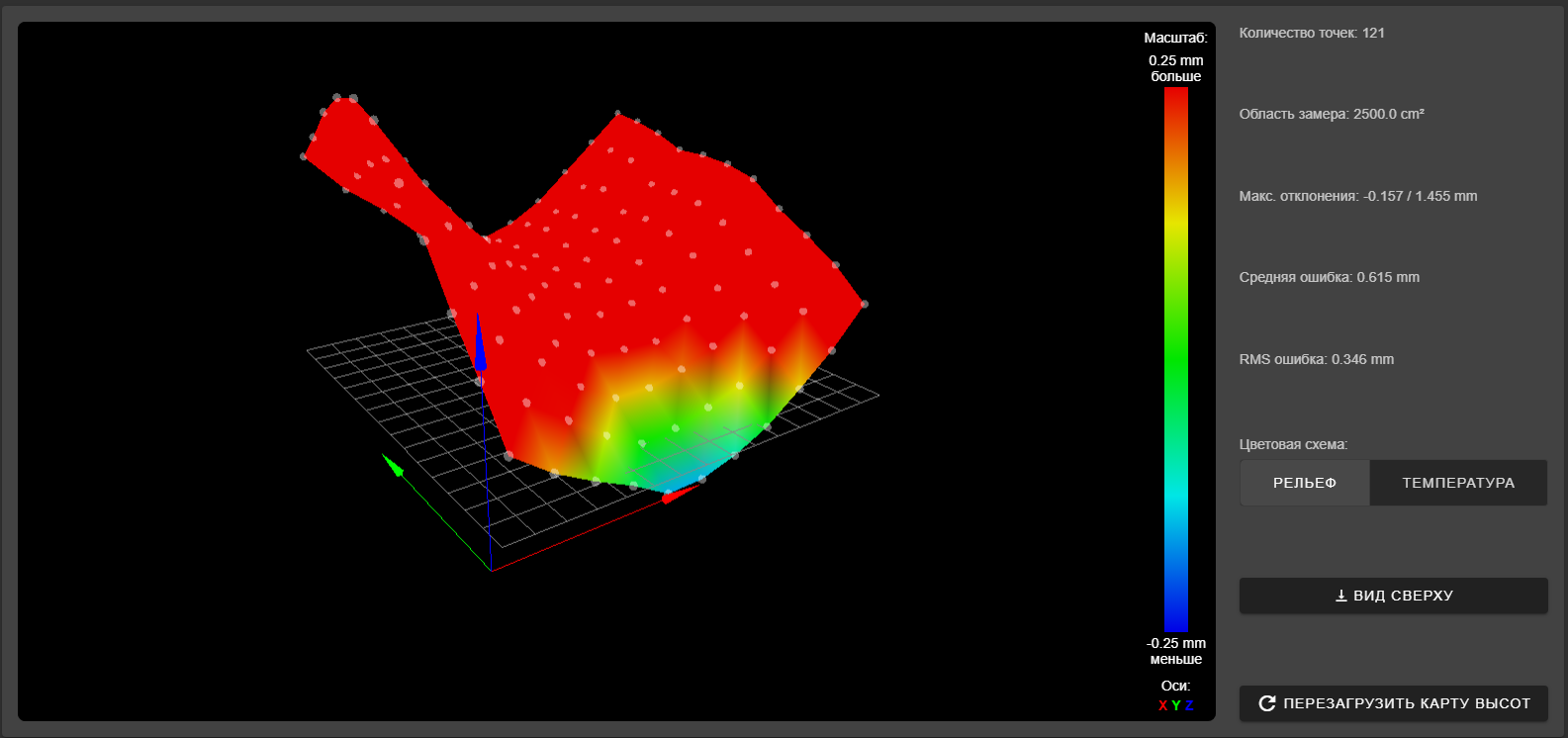
                    Yes, the table is really ragged. But what does it matter?

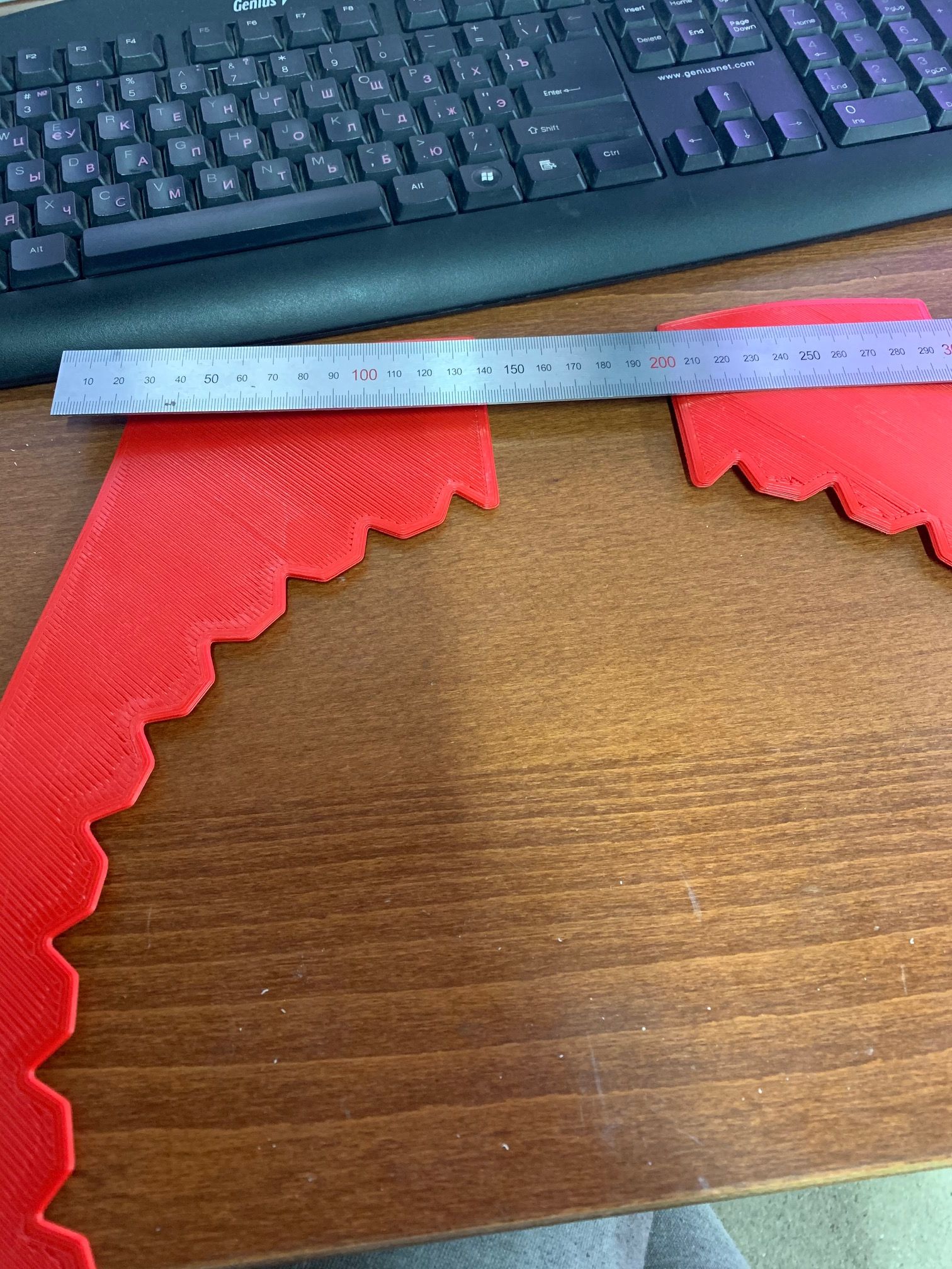
                    RepRapFirmware height map file v2 generated at 2019-11-01 19:53, min error -0.157, max error 1.455, mean 0.615, deviation 0.346
                    xmin,xmax,ymin,ymax,radius,xspacing,yspacing,xnum,ynum
                    450.00,950.00,120.00,620.00,-1.00,50.00,50.00,11,11
                      0.311,  0.163,  0.054, -0.041, -0.157, -0.153, -0.096, -0.007,  0.135,  0.285,  0.481
                      0.538,  0.388,  0.246,  0.109,  0.003,  0.019,  0.069,  0.128,  0.265,  0.423,  0.625
                      0.749,  0.588,  0.436,  0.264,  0.150,  0.147,  0.190,  0.264,  0.378,  0.504,  0.729
                      0.988,  0.760,  0.609,  0.402,  0.303,  0.273,  0.265,  0.342,  0.466,  0.623,  0.821
                      1.175,  0.966,  0.754,  0.567,  0.426,  0.389,  0.408,  0.439,  0.588,  0.733,  0.941
                      1.392,  1.108,  0.892,  0.671,  0.523,  0.485,  0.468,  0.534,  0.659,  0.795,  0.985
                      1.455,  1.171,  0.922,  0.739,  0.558,  0.514,  0.530,  0.602,  0.694,  0.816,  1.001
                      1.438,  1.153,  0.944,  0.734,  0.558,  0.535,  0.558,  0.613,  0.688,  0.823,  1.000
                      1.352,  1.097,  0.919,  0.732,  0.618,  0.532,  0.606,  0.649,  0.783,  0.928,  1.065
                      1.211,  1.003,  0.823,  0.625,  0.536,  0.518,  0.587,  0.633,  0.756,  0.955,  1.108
                      1.086,  0.891,  0.752,  0.581,  0.519,  0.491,  0.552,  0.658,  0.813,  0.972,  1.133
                    

                    In the photo there is a fragment of a part that covers several calibration points. Why is this place not aligned?

                    Is it possible that the firmware has restrictions on the height of the table when adjusting?

                    IMG_1174.jpg
                    IMG_1175.jpg
                    IMG_1176.jpg

                    I changed the calibration settings

                    M208 X0 Y-35 Z0 S1 ; set axis minima
                    M208 X1380 Y1210 Z1500; Set axis maxima
                    
                    M557 X450:950 Y120:620 S50
                    M376 H6
                    
                    1 Reply Last reply Reply Quote 0
                    • Vetiundefined
                      Veti
                      last edited by

                      it means that your bed is very uneven. as you have 0.2 differences between probing point (an entire layer) there is only so much that the mesh can compensate for. you will need a lot smaller spacing i would imagine.

                      can you post a picture of the mesh.

                      1 Reply Last reply Reply Quote 0
                      • Depundefined
                        Dep
                        last edited by

                        Do you want to say that mesh calibration cannot compensate for more than 0.2mm?

                        2019-11-03_12-47-04.png

                        1 Reply Last reply Reply Quote 0
                        • Vetiundefined
                          Veti
                          last edited by

                          that looks absolutly terrible.

                          i am saying that if you have 0.2 between two points the area in between is calculated, so there could be deviations to the real values.
                          with a bed as uneven as that it is very likely that that is the case.

                          however looking at our printer setup, it could also be a mechanical issue with your x gantry. because of the length it could be sagging and produces this result.

                          1 Reply Last reply Reply Quote 0
                          • Depundefined
                            Dep
                            last edited by

                            All axes are calibrated and checked. Dimensions of printed part + - 0.2 mm

                            OK. The table is very uneven. But for calibration, what does it matter?

                            Why doesn't calibration work in this range?

                            Is there a limitation?

                            1 Reply Last reply Reply Quote 0
                            • Vetiundefined
                              Veti
                              last edited by

                              @Dep said in Mesh calibration not working or what am I doing wrong?:

                              All axes are calibrated and checked. Dimensions of printed part + - 0.2 mm

                              axis sagging has nothing to do with dimension.

                              your x axis and y axis are over a meter long. they could bend under their own weight of the beam is not rigid enough.
                              that would lead to an image you are seeing, where the sides are higher and the middle is low. i.e the weight in the middle is causing more deflection that on the sides.

                              1 Reply Last reply Reply Quote 0
                              • Depundefined
                                Dep
                                last edited by

                                Yes, I understand that.

                                But mesh calibration measures this deflection. Why is it not compensated during printing?

                                1 Reply Last reply Reply Quote 0
                                • Vetiundefined
                                  Veti
                                  last edited by

                                  @Dep said in Mesh calibration not working or what am I doing wrong?:

                                  M557 X500:1000 Y150:600 S25

                                  thy with M557 X500:1000 Y150:600 S10

                                  Depundefined 1 Reply Last reply Reply Quote 0
                                  • Depundefined
                                    Dep @Veti
                                    last edited by

                                    @Veti said in Mesh calibration not working or what am I doing wrong?:

                                    thy with M557 X500:1000 Y150:600 S10

                                    This is unfortunately impossible 😞 The maximum number of points is 121

                                    1 Reply Last reply Reply Quote 0
                                    • Depundefined
                                      Dep
                                      last edited by

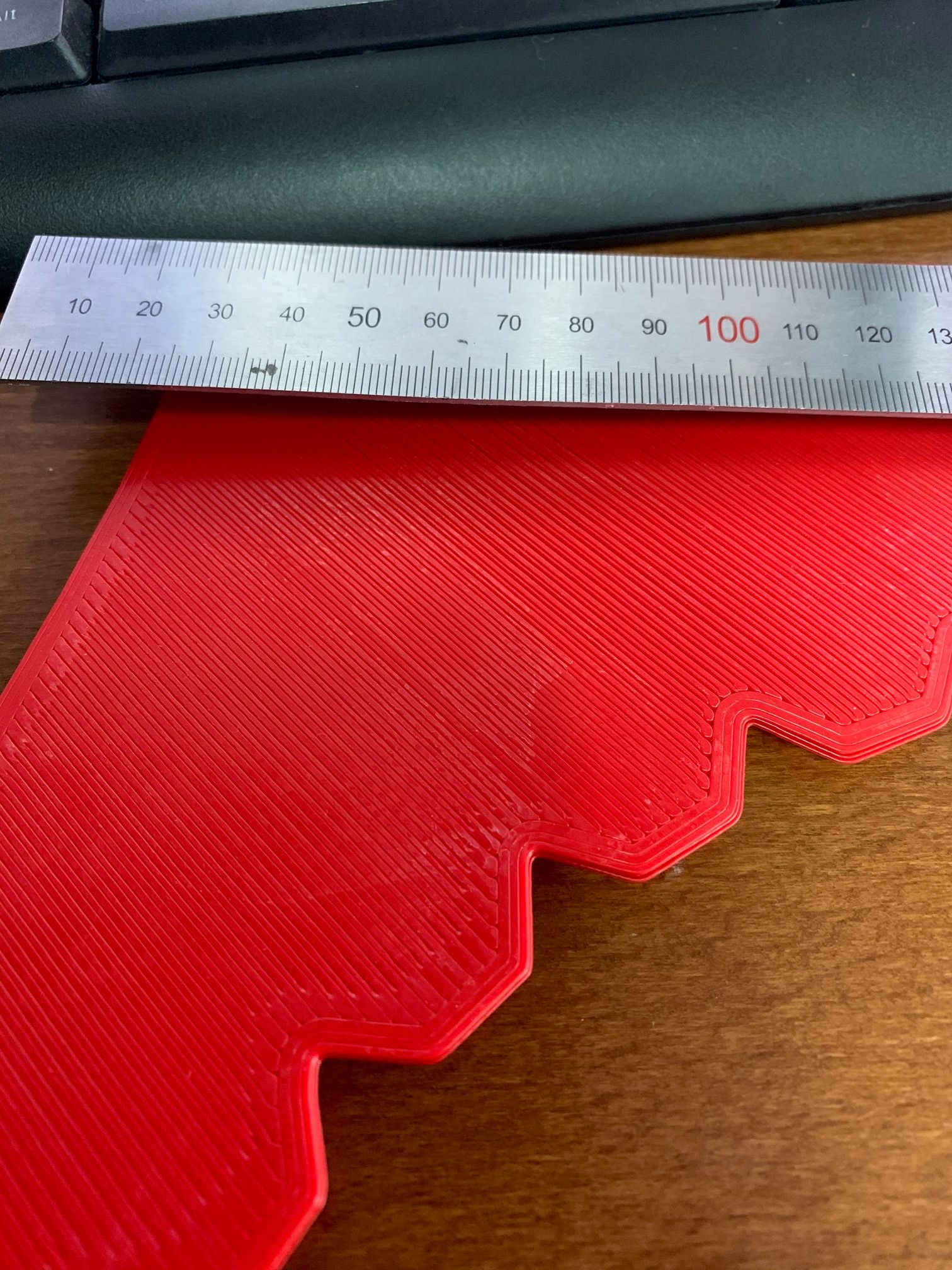
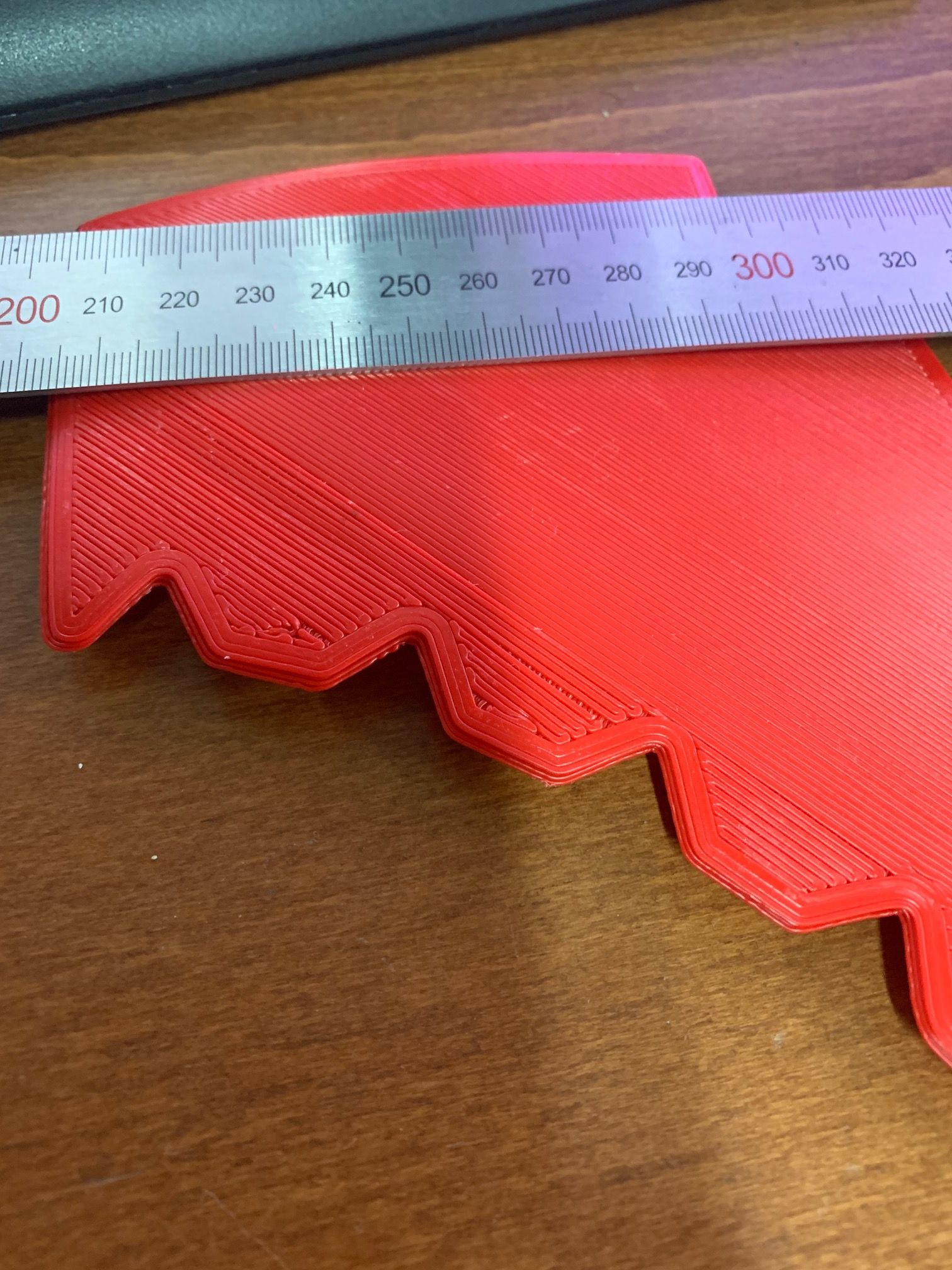
                                      But part of the model in the photo falls into several calibration points. Why are they not aligned?

                                      1 Reply Last reply Reply Quote 0
                                      • Vetiundefined
                                        Veti
                                        last edited by

                                        @Dep said in Mesh calibration not working or what am I doing wrong?:

                                        The maximum number of points is 121

                                        https://duet3d.dozuki.com/Wiki/Using_mesh_bed_compensation

                                        There is a firmware-dependent limit on the number of 441 probe points allowed.

                                        1 Reply Last reply Reply Quote 0
                                        • Depundefined
                                          Dep
                                          last edited by

                                          I have a 0.8.5 board. And when i try to make more than 121 points, it gives an error.

                                          But even with this number of points. They overlap the model. Why is it not calibrated.

                                          I think there is some kind of limit on the calibration height.

                                          I have spent many days and can not solve this problem.
                                          There is no technical possibility to make a flat table on such sizes.

                                          I don’t know what to do next. 😞

                                          1 Reply Last reply Reply Quote 0
                                          • Vetiundefined
                                            Veti
                                            last edited by

                                            what firmware version are you using?

                                            1 Reply Last reply Reply Quote 0
                                            • First post
                                              Last post
                                            Unless otherwise noted, all forum content is licensed under CC-BY-SA