Z probe questions - Where is Home and Inductance v BLTouch
-
This I'm afraid is a case of the more I read the more confused I get .... I'm building and setting up a CoreXY. Total bed size is 330x330, I have designed for using a Prusa V2 PINDA probe for bed levelling although I do have a V2 BLTouch on the shelf.
Please bear with me as I may be totally misreading all the information provided in documentation.
Q1 : Just 'how' do you tell the system where home actually is - the cartesian point in space upon which all other moves are based.
I'd like to tell the machine that the home is actually the centre of the build area and NOT one of the extremes of axis. I do plan to put MIN POS end stops on X, Y and MAX POS on Z. Logically I believe I drive to these end points thus (from Dozuki)
my homeall.g file would look like
G91 ; relative mode
G1 S1 X-310 F3000 ; coarse home X
G1 X4 F600 ; move away from the X endstop
G1 S1 X-10 ; fine home X
G1 S1 Y-310 ; coarse home Y
G1 Y4 F600 ; move away from the Yendstop
G1 S1 Y-10 ; fine home Y
G1 S1 Z310 F1200 ; coarse home Z
G1 S1 Z-4 F300
G1 S1 Z-10 ; fine home Z
G1 S1 Z-200 F1200 ; return build plate close to top of frame ready for levelling
G1 S1 X155 Y155 F3000 ; move nozzle to centre of bed
I plan to set up my slicers for centre of bed being 'home' and I don't see how this works since I believe to the slicer that X,Y becomes 0,0 and not 155,155 as it would be in my case. I park the bed at the bottom of the frame after prints.
so I plan to use
M208 X-160:155 Y-155:160 ; set axis limits
Am i in the right zone - ? - this just doesn't look right - why is the switch trigger number swapped for X and Y why no 'Z' are we relying on the probe to trigger (dangerous but engineering for a switch when the bed is high (close to nozzle) will almost certainly result in collision with nozzle at some point (has happened a couple of times on the Prusa - my fault entirely but a direct result of PINDA height setting) which is something I want to avoid (linear rails are unforgiving) - has my confusion entered the twilight zone ...
Q2: Should I redesign my hot end to suit a BLTouch instead of messing with an inductance probe (I am using a Wham Bam build surface) - I'm reluctant because I'll lose dimensions in X due to the larger size of the BLTouch.
-
@Garfield said in Z probe questions - Where is Home and Inductance v BLTouch:
my homeall.g file would look like
there is no G30 in your homeall.
please post your config.the coordingates for homeing are the x and y parameter of the G30 command.
-
I have no G30 in config.g or homeall.g - I started config based on the RRF config tool but that isn't entirely up to date for Duet 3 firmware.
I don't do any probing in the homeall - I use end stops - my end stop for Z is actually the furthest point I can lower the bed (Z) away from the nozzle. I would never rely on 'probing' to set a limit - only levelling.
This is my bed.g
M561 ; clear any bed transform G28 ; home (runs homeall.g) G30 P0 X0 Y0 Z-99999 ; probe near front left leadscrew G30 P1 X310 Y0 Z-99999 ; probe near front right leadscrew G30 P2 X150 Y310 Z-99999 S3 ; probe near rear centre leadscrew and calibrate 3 motors G29 ; probe the bed and enable compensation -
PPS - I am not talking about 'homeing' - this is partly where a lot of confusion is creeping in I think.
When I say 'home' I mean the cartesian coordinates that the printer considers home - which I want to be in the centre of the bed and NOT at the front left corner as is typical (and where my end stops are).
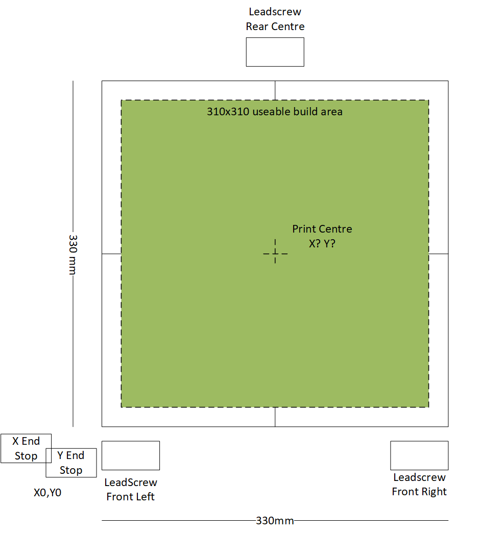
I do this so that my gcode will work on any printer type since the centre of the print is the centre of the bed - which actually makes my bed.g incorrect since the front left leadscrew is X-170 Y-160 from centre of the bed - assuming that the centre of the bed is X0, Y0 - since I've told the printer that the switch triggers at -160 with a print limit at -155 - I'll do a drawing and post it in a few mins.
-
@Veti so this shows my bed arrangement. I'm pretty sure that the printer will regard the endstops as whatever I define the position as - so if I define the switch as triggering at -160 using the M208 code then the printer will regard that as -160 and not 0.
-
You can choose the X=0 Y=0 position to be wherever you want. See https://duet3d.dozuki.com/Wiki/Centering_the_bed_or_setting_the_bed_origin. The X=0 Y=0 position is not necessarily where the printer moves the print head in order to establish a known position - that can be anywhere convenient.
-
So if I use this command
M208 X-160:155 Y-155:160 ; set axis limits
the printer knows that the switches trigger at -ve X and -ve Y - when the axis position is X0,Y0 it should be in the centre of the bed, the build area starts at X-155 and Y-155 - is this a correct analysis ?
-
@Garfield said in Z probe questions - Where is Home and Inductance v BLTouch:
my end stop for Z is actually the furthest point I can lower the bed (Z) away from the nozzle. I would never rely on 'probing' to set a limit - only levelling.
The problem with this approach is that you are relying on your Z max position to be exactly the same relative to the bed surface and never change. The probe however will always be locating the current actual position of the bed. This isn't a deal breaker but you do have to work around it. Here's an example of a macro that uses the probe to find Z0 and then sets the Z axis length for the z max endstop so that it's accurate. https://duet3d.dozuki.com/Guide/Ender+3+Pro+and+Duet+Maestro+Guide+Part+5:+Upgrades/54#s221
Also, before you do a G29 or even initiate an actual print you should do a single G30 at the center of the bed just to establish Z0 difinitively.
-
I was planning on an end switch mounted on each of the 3 Z leadscrews which are fixed to the bed.
This is just to get them back into a known state.
I still plan on Z probing to set the final first layer height / mesh bed level etc.
I've designed for an induction probe (Prusa's) but I'm also considering putting a BLTouch into service.
I guess I'd need to to an offset for the probe - which for my induction probe is X-27 Y-7 from the nozzle tip centre to centre - but I've not got that far yet.