Trying to set starting point that is not at the end stops
-
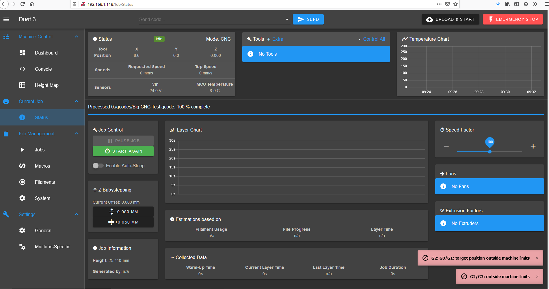
@dc42 I am getting these errors now when i hit G10 L20 P1 X0 Y0 Z0
This is my sys file.
; Configuration file for Duet 3 (firmware version 3)
; executed by the firmware on start-up
;
; generated by RepRapFirmware Configuration Tool v2.1.8 on Wed Feb 19 2020 06:47:06 GMT+0000 (Greenwich Mean Time); General preferences
G90 ; send absolute coordinates...
M83 ; ...but relative extruder moves
M550 P"Duet 3" ; set printer name; Drives
M569 P0.0 S1 ; physical drive 0.0 goes forwards
M569 P0.1 S1 ; physical drive 0.1 goes backwards
M569 P0.2 S0 ; physical drive 0.2 goes backwards
M569 P0.3 S0 ; physical drive 0.3 goes backwards
M584 X0.0:0.3 Y0.1 Z0.2 ; set drive mapping
M350 X16 Y16 Z16 E16 I1 ; configure microstepping with interpolation
M92 X80.00 Y80.00 Z400.00 E80.00 ; set steps per mm
M566 X900.00 Y900.00 Z12.00 E900.00 ; set maximum instantaneous speed changes (mm/min)
M203 X10000.00 Y10000.00 Z500.00 E10000.00 ; set maximum speeds (mm/min)
M201 X1200.00 Y1200.00 Z200.00 E1200.00 ; set accelerations (mm/s^2)
M906 X1200 Y1200 Z1400 E1200 I30 ; set motor currents (mA) and motor idle factor in per cent
M84 S30 ; Set idle timeout; Axis Limits
M208 X0 Y0 Z0 S1 ; set axis minima
M208 X2498 Y1230 Z135 S0 ; set axis maxima; Endstops
M574 X1 S1 P"io0.in" ; configure active-high endstop for low end on X via pin io0.in
M574 Y1 S1 P"io1.in" ; configure active-high endstop for low end on Y via pin io1.in
M574 Z2 S1 P"io2.in" ; configure active-high endstop for high end on Z via pin io2.in; Z-Probe
M558 P0 H5 F120 T6000 ; disable Z probe but set dive height, probe speed and travel speed
;M557 X15:215 Y15:195 S20 ; define mesh grid; Heaters
M308 S0 P"temp0" Y"thermistor" T100000 B4138 ; configure sensor 0 as thermistor on pin temp0
M950 H0 C"out0" T0 ; create bed heater output on out0 and map it to sensor 0
M143 H0 S0 ; set temperature limit for heater 0 to 120C
M307 H0 B0 S1.00 ; disable bang-bang mode for the bed heater and set PWM limit; Fans
; Tools
; Custom settings
M453 P2 F400 ; spindle forward/reverse on heater 3&4 pins, PWM frequency 400Hz
M564 H0
M140 H-1 ; Disable heated bed
; Miscellaneous
M911 S10 R11 P"M913 X0 Y0 G91 M83 G1 Z3 E-5 F1000" ; set voltage thresholds and actions to run on power loss -
The messages indicate that the error is caused by a G2 or G3 arc movement being commanded, which can't be completed because it would require moton outside the machine limits. Are you certain that you can move the tool head through the whole available XY range?
Duet WiFi hardware designer and firmware engineer
Please do not ask me for Duet support via PM or email, use the forum
http://www.escher3d.com, https://miscsolutions.wordpress.com -
@dc42 Yes I’ve been able to jog the machine to each corner.
-
@dc42 Ok ive been playing with it more and it was the cut that i was trying to perform. Thank you for the help
-
@dc42 Sorry to keep bugging but I cant rap my brain around this. So from where I have my computer attached to my CNC the far back left corner is where the X and Y end stops are located. So when i homeall everything goes to the far left back corner and the Z axis moves as high as it can till it hits the endstop. Everything on the DWC shows 0.0 for alignment. However because of where the computer is located i would like to line up my material from the close edge. So I am trying to use the far left close edge as my X0 Y0 points. I line up the spindle to my starting point hit my G10 L20 P1 X0 Y0 Z0 command then I try to run my cut and I get G0/G1target limit outside of machine area. I know it has to do with negative and positive numbers but just confused as to what needs to be what.
-
@chichirod said in Trying to set starting point that is not at the end stops:
@dc42 Sorry to keep bugging but I cant rap my brain around this. So from where I have my computer attached to my CNC the far back left corner is where the X and Y end stops are located. So when i homeall everything goes to the far left back corner and the Z axis moves as high as it can till it hits the endstop. Everything on the DWC shows 0.0 for alignment.
That doesn't sound right. When you jog the axes, which directions are +X and +Y? Normally, +X is to the right, and +Y is towards the back. In which case, back left would be X zero and Y max, instead of both zero. Other configurations are possible, but when viewed from above +Y must be 90deg anticlockwise from +X.
Duet WiFi hardware designer and firmware engineer
Please do not ask me for Duet support via PM or email, use the forum
http://www.escher3d.com, https://miscsolutions.wordpress.com -
@dc42 When I jog it +X is moving to the right and +Y is moving towards the front.
-
@dc42 For simplicity (for me more so then you)it wouldnt be very hard for me to relocate my endstops to the front left corner and then just change the direction of the motors or am I just confusing the issue more?
-
You don't need to move the endstops. It's the M574 command that specifies the location of the endstop, either at the high end or low end. They don't need to be on the low end. And in fact, whether you call it high or low is entirely up to your definition of what is high and low. Typically, you want to use a right handed coordinate system.
So if you make that gesture with your right hand (and just point the Z axis up) you see that X+ is to the right, Y+ away from you, and Z+ goes up. That's what's meant by right hand coordinate system.
It basically follows the cartesian coordinate system. Like graphing paper.
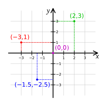
Using a right handed system matches what cad and slicing software uses, so that you don't get mirrorer parts, or have axis that move different than expected.
In your case, you need to decide where you want 0,0 to be, and then apply the right hand coordinate system to that. Then the location of the endstops need to be defined in M574, and the directions of rotation of the motors need to match to produce the expected linear motion direction, and then your homing files need to be set to use movements that move towards the endstops.
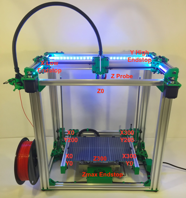
This is different than your machine obviously, but it illustrates the idea.I would suggest doing a similar picture for your own machine to help you work it out. Remember that it's all arbitrary. You need to decide what the front of the machine is, and then work from there, keeping the right hand rule in play.
-
@Phaedrux Thank you this is awesome info