Piezo20 probe and piezo kit now available
-
It is on a delta I have seen the pics
-
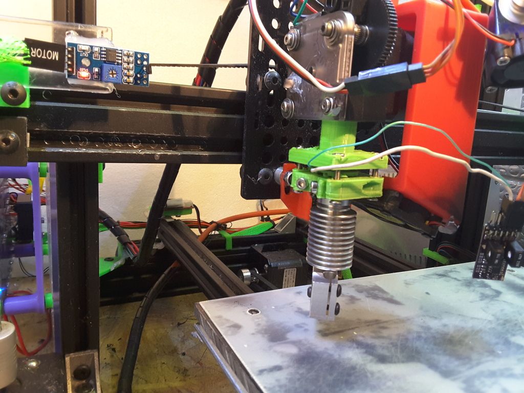
It's a kossel mini, originally a T3P3 kit but I think only the vertices and extrusions are original now.

The heated bed is supported on three of these, printed in ABS.

I'm looking at alternatives to the printed support, the ABS is not holding up to the temperature in the long run and the tops of the posts are starting to deform.
I'm happy to post .stl or .step files but unless your printer is identical to mine the mounting holes will not line up with your heated bed. You're better off modelling your own.
The three piezo disks are wired in parallel to the single input of a V1.0 board.
Idris
-
Yes but the Step files will give me an idea of how you have mounted everything.
I am tempted to do something and get them CNC'd in Alluminium (I am thinking of purchasing a smal Mill in the next few weeks and the CNC version is not to much more than the Manual one tho it comes without a controller or software but I already have all of that)
So if you could post the files it would be appreciated and Maybe when I get set up I could do you a set of yours in Ally?
Doug
(A bit of Payback lol)
-
I've emailed you the file.
Idris
-
Thanks Idris I'll see what I can do with it
-
Wow, a world of difference using this probe after a couple of minutes setting up:
For testing:
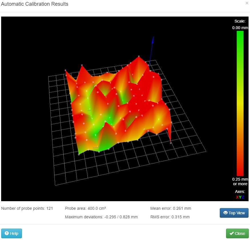
This is what I got with DC42's sensor AFTER spraying my aluminium heat bed with black matt paint and probing my Printbite (the sticky tape makes it a bit patchy as in the photo - is this causing the problem?):
With the piezo board:
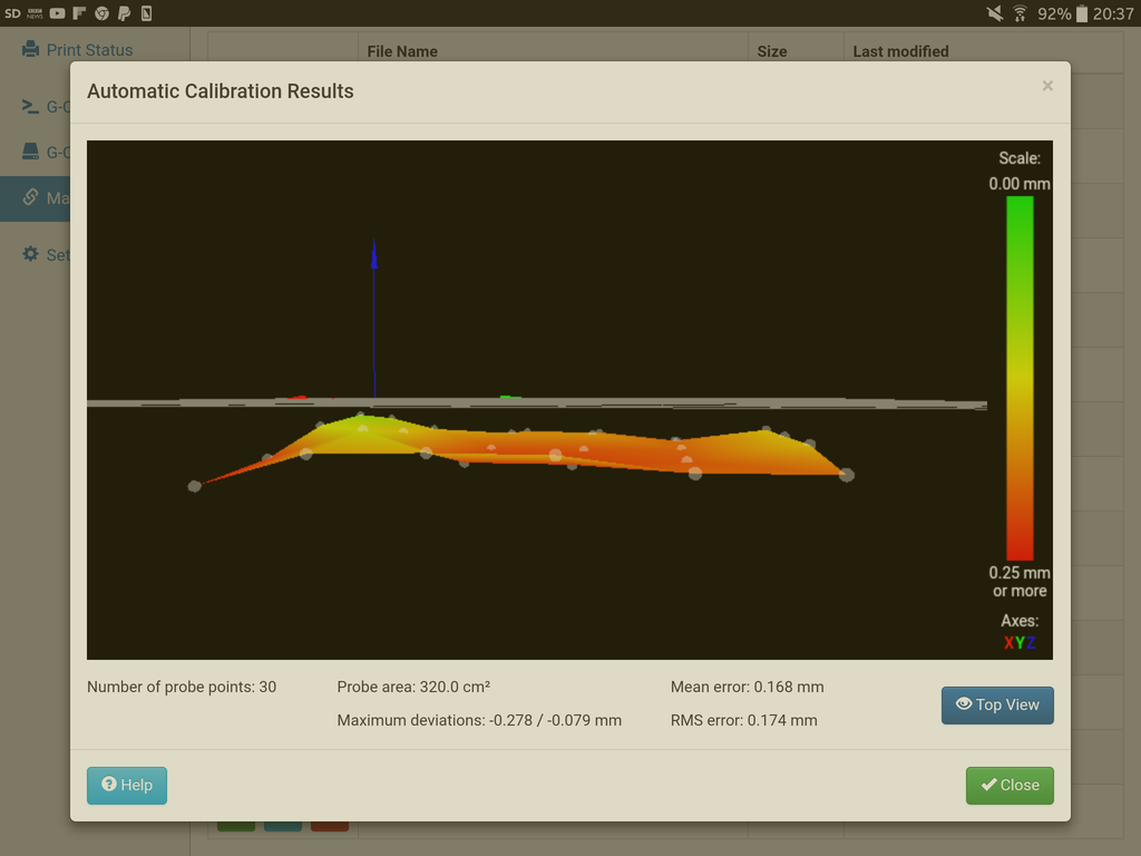
A massive difference…
Cant figure out why it is showing under the horizon through.
-
Its probably the probe. In order to get a trigger you have to push down past "z=0" to get it to trigger. So maybe put -0.15 z offset in your G31 command. Then try again.
-
Do a paper test to set your z-height, just like you would with any other probe:
Move the nozzle manually until it grips a sheet of paper.
Then:
G92 Z0
G1 Z5
G30 S-1Record the point that stops at, and put it as the trigger point in your G31.
-
Wow, a world of difference using this probe after a couple of minutes setting up:
…This is what I got with DC42's sensor AFTER spraying my aluminium heat bed with black matt paint and probing my Printbite (the sticky tape makes it a bit patchy as in the photo - is this causing the problem?):Yes, the variable reflection from the sticky tape is the problem. With PEI you have to spray paint the back of the PEI matt black, cure it in an oven, then stick it painted side down to the bed plate. I imagine PrintBite is similar.
-
Re. the z offset, just tried this myself, I was using 0.15 z-offset in slic3r, now I have it in my G31(as -0.15). It works fine, really nice "only just squashed enough to get it to stick" first layer.
-
And don't forgot you can do an "auto first layer" height calibration by sending G30 (RRF) G30 Z0 (smoothie) after levelling/calibration to recheck z=0 and reset it (from bed centre ideally but shouldn't matter if your calibration/levelling are accurate). Assuming you set the z-probe offset correctly you should now get exactly the first layer height you sliced.
Its worth checking the offset with something thinner than paper if you have something that would work.
-
such as a very thin Feeler gauge like the 0.05mm one from this set from Halfords http://www.halfords.com/workshop-tools/tools/hand-tools/halfords-feeler-gauge-metric-and-imperial-16-blades
Doug
Got some 3mm thick PEI Sheet on it's way to me as well
-
And don't forgot you can do an "auto first layer" height calibration by sending G30 (RRF) G30 Z0 (smoothie) after levelling/calibration to recheck z=0 and reset it (from bed centre ideally but shouldn't matter if your calibration/levelling are accurate). Assuming you set the z-probe offset correctly you should now get exactly the first layer height you sliced.
Its worth checking the offset with something thinner than paper if you have something that would work.
Is there a reference for using G30 after a bed level is done? Can it be done after mesh levelling? I must have missed that.
-
Ive done the
G92 Z0
G1 Z5
G30 S-1and it reports a value of 0.0x across the bed.
When printing it drops below the z0 plane and hits my printbite.@DC42: OK, when I rip it apart, I'll try spraying the rear of the printbite to see what effect it has.
-
Kraegar - reference, not really but it was discussed here: https://www.duet3d.com/forum/thread.php?id=940#p9288
Yes you can do it after mesh levelling it does not clear the mesh (or calibration) it merely probes and resets z to the probed point.Phytone - You dont need the G92 Z0. Just run mesh/calib. then go to centre
G1 Z5
G30You don't need the S-1 this parameter is only information and reports the height difference.
Try that and then see. You height map I am not sure why thats low, can you attach/post your config.g? And Bed.g? -
Did the above, same issue.
; bed.g
; called to perform automatic bed compensation via G32
;
; generated by RepRapFirmware Configuration Tool on Sat Feb 04 2017 22:32:57 GMT+0000 (GMT Standard Time); Clear any bed transform
M561; Probe the bed at 5 points
G30 P0 X50 Y50 H2 Z-99999
G30 P1 X50 Y215 H2 Z-99999
G30 P2 X215 Y50 H2 Z-99999
G30 P3 X215 Y215 H2 Z-99999 S -
; Configuration file for Duet WiFi (firmware version 1.17)
; executed by the firmware on start-up
;
; generated by RepRapFirmware Configuration Tool on Sat Feb 04 2017 22:32:57 GMT+0000 (GMT Standard Time); General preferences
M111 S0 ; Debugging off
G21 ; Work in millimetres
G90 ; Send absolute coordinates…
M83 ; ...but relative extruder moves
M555 P2 ; Set firmware compatibility to look like Marlin
M208 X0 Y0 Z0 S1 ; Set axis minima
M208 X230 Y230 Z200 S0 ; Set axis maxima; Endstops
M574 X1 Y1 Z0 S0 ; Define active low and unused microswitches
M558 P1 I1 F500 X0 Y0 Z0 ;analogue piezo sensor output falls on contact, probing speed, not used to home axes
G31 X0 Y0 Z0.03 P700 ;sensor is nozzle and trigger value; Drives
M569 P0 S0 ; Drive 0 goes backwards
M569 P1 S0 ; Drive 1 goes backwards
M569 P2 S0 ; Drive 2 goes backwards
M569 P3 S1 ; Drive 3 goes forwards
M350 X16 Y16 Z16 E16 I1 ; Configure microstepping with interpolation
M92 X80.5 Y80.5 Z405.9 E455.9 ; Set steps per mm
M566 X900 Y900 Z12 E120 ; Set maximum instantaneous speed changes (mm/min)
M203 X8000 Y8000 Z180 E2200 ; Set maximum speeds (mm/min)
M201 X800 Y800 Z250 E800 ; Set accelerations (mm/s^2)
M906 X1000 Y1000 Z800 E1000 I30 ; Set motor currents (mA) and motor idle factor in per cent
M84 S30 ; Set idle timeout; Heaters
M143 S260 ; Set maximum heater temperature to 260C
M305 P0 R4700 T100000 B3950; Set thermistor + ADC parameters for heater 0
M305 P1 T100000 B4138 C0 R4700 ; Set thermistor + ADC parameters for heater 1; Tools
M563 P0 D0 H1 ; Define tool 0
G10 P0 X0 Y0 ; Set tool 0 axis offsets
G10 P0 R0 S0 ; Set initial tool 0 active and standby temperatures to 0C; Network
M550 PPhytone ; Set machine name
M552 P0.0.0.0 S1 ; Enable network and acquire dynamic address via DHCP; Fans
M106 P0 S0.3 I0 F500 H-1 ; Set fan 0 value, PWM signal inversion and frequency. Thermostatic control is turned off
M106 P1 S1 I0 F500 H1 T45 ; Set fan 1 value, PWM signal inversion and frequency. Thermostatic control is turned on
M106 P2 S1 I0 F500 H1 T45 ; Set fan 2 value, PWM signal inversion and frequency. Thermostatic control is turned on; Custom settings are not configured
-
RepRapFirmware height map file v1, mean error -0.20, deviation 0.04
xmin,xmax,ymin,ymax,radius,spacing,xnum,ynum
60.00,240.00,35.00,220.00,-1.00,40.00,5,5
-0.119, -0.143, -0.094, -0.183, -0.207
-0.205, -0.220, -0.178, -0.092, -0.198
-0.215, -0.205, -0.237, -0.244, -0.173
-0.242, -0.230, -0.210, -0.225, -0.225
-0.230, -0.190, -0.188, -0.156, -0.274 -
and this is the start of a g-code file
;FLAVOR:RepRap
;TIME:2049
;Filament used: 3.66315m
;Layer height: 0.3
;Generated with Cura_SteamEngine 2.4.0
M190 S70
M104 S190
M109 S190
G21 ;metric values
G90 ;absolute positioning
M82 ;set extruder to absolute mode
M107 ;start with the fan off
G28 X0 Y0 ;move X/Y to min endstops
G28 Z0 ;move Z to min endstops
G1 Z1.0 F9000 ;move the platform down 1mm
G92 E0 ;zero the extruded length
G1 F200 E3 ;extrude 3mm of feed stock
G92 E0 ;zero the extruded length again
G1 F9000
M117 Printing…
;LAYER_COUNT:83
;LAYER:0
M107
G1 F1800 E-4
G0 F3600 X102.801 Y104.451 Z0.3
;TYPE:SUPPORT
G1 F1800 E0
G1 X137.199 Y104.451 E1.63032
G1 X137.199 Y135.549 E3.10423
G1 X102.801 Y135.549 E4.73455
G1 X102.801 Y104.451 E6.20846
G1 F1800 E2.20846
G0 F3600 X113.873 Y114.036
G0 X113.955 Y114.11
G1 F1800 E6.20846 -
adding G31 Z-0.2 or G31 Z0.2
or extremes like G31 Z-4 or G31 Z 4into the config.g file has NO impact whatsoever.
I'm stumped.


