Help please, radius curves have choppy motion causing artifact
-
OK, I need some help this has driven me crazy for a while
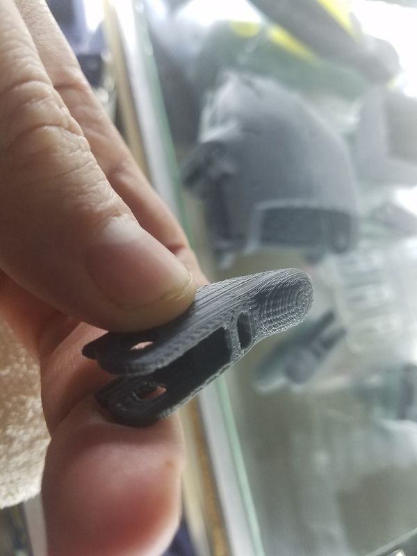
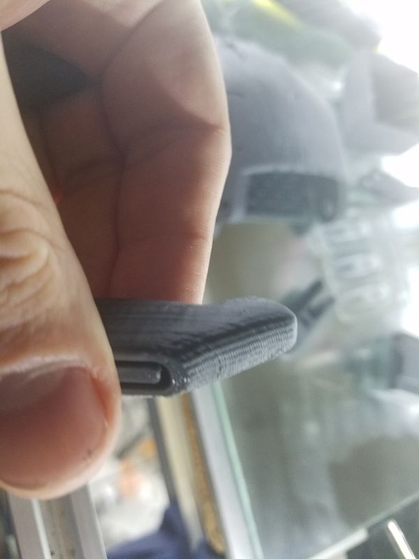
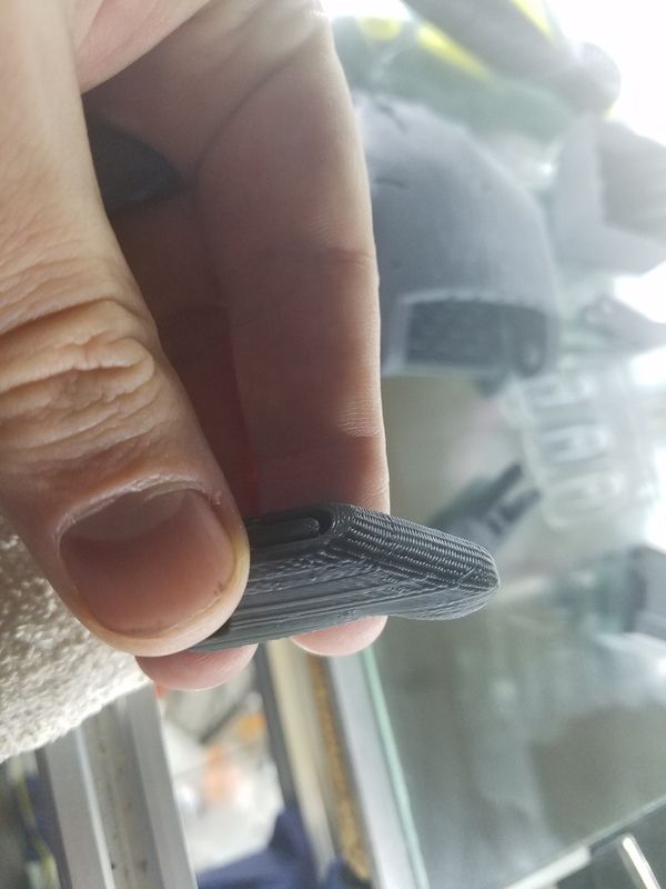
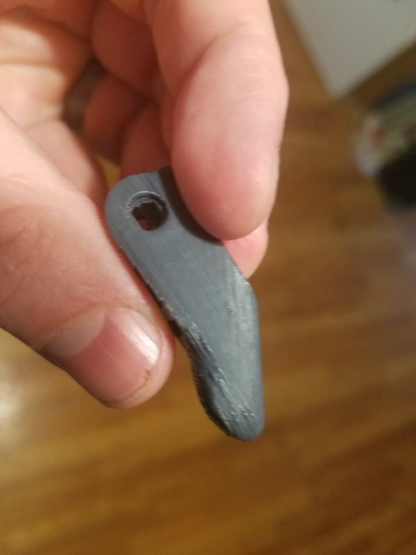
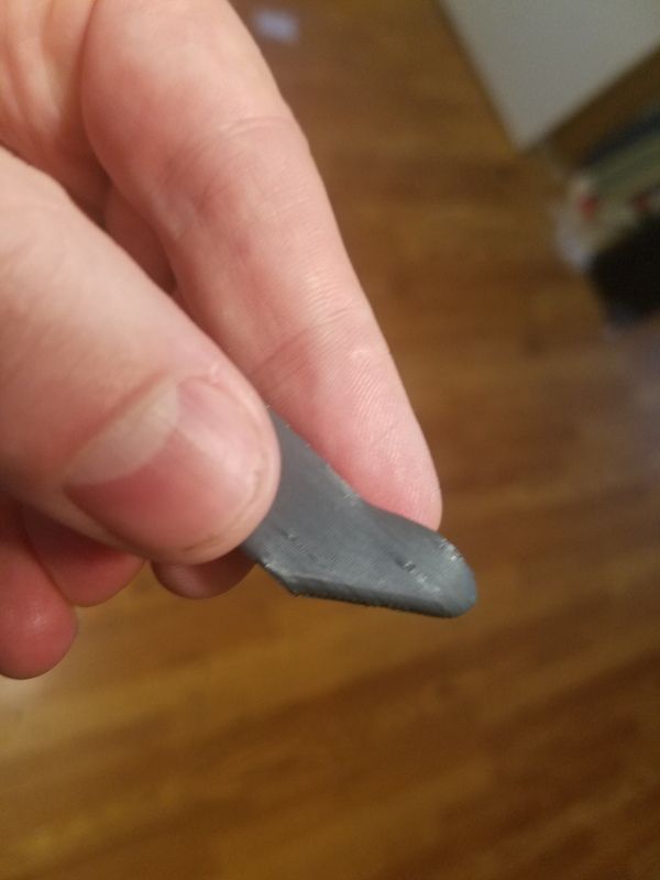
You'll notice in the pictures that on the small radius of the fingers that there are basically ridges that are created from jerky movement along the radius of the part. Any suggestions would be greatly appreciated, I'm at a loss at this point, my speculation is that it is something in the accel and jerk, but i've tried so many different combinations that I need a set of fresh eyes on it.
The Machine is a CoreXY C-bot
; Communication and general M111 S0 ; Debug off M550 PCoreXY ; Machine name and Netbios name (can be anything you like) M551 Preprap ; Machine password (used for FTP) ;*** If you have more than one Duet on your network, they must all have different MAC addresses, so change the last digits M540 P0xBE:0xEF:0xDE:0xAD:0xFE:0xED ; MAC Address ;*** Wifi Networking M552 S1 ; Enable WiFi M555 P2 ; Set output to look like Marlin M575 P1 B57600 S1 ; Comms parameters for PanelDue ; Axis and motor configuration M667 S1 ; switch to CoreXY mode M569 P0 S1 ; Drive 0 goes forwards (change to S0 to reverse it) M569 P1 S0 ; Drive 1 goes backwards M569 P2 S0 ; Drive 2 goes forwards M569 P3 S1 ; Drive 3 goes forwards M569 P4 S1 ; Drive 4 goes forwards M350 X128 Y128 Z32 E16 I0 ; set 16x microstepping with interpolation M574 X1 Y1 Z1 S0 ; set homing switch configuration (All Active, at low end, active low) M906 X1000 Y1000 Z1000 E1200 ; Set motor currents (mA) M201 X3000 Y3000 Z15 E10000 ; Accelerations (mm/s^2) M203 X15000 Y15000 Z100 E3600 ; Maximum speeds (mm/min) M566 X180 Y180 Z30 E300 ; Maximum jerk speeds mm/minute M208 X300 Y300 Z300 ; set axis maxima and high homing switch positions (adjust to suit your machine) M208 X0 Y0 Z0 S1 ; set axis minima and low homing switch positions (adjust to make X=0 and Y=0 the edges of the bed) M92 X752 Y752 Z1790.98 ; set axis steps/mm M92 E421:421 ; set extruder 0 and 1 steps/mm G21 ; Work in millimetres G90 ; Send absolute coordinates... M83 ; ...but relative extruder moves ; Thermistors M305 P0 T100000 B4267 R4700 H0 L0 ; Put your own H and/or L values here to set the bed thermistor ADC correction M305 P1 T100000 B4267 R4700 H0 L0 ; Put your own H and/or L values here to set the first nozzle thermistor ADC correction M307 H1 A300.2 C87.1 D4.4 B0 ; Fans M106 P1 H1 T50 ; enable thermostatic mode for fan 1 ; Tool definitions M563 P0 D0 H1 ; Define tool 0 G10 P0 S0 R0 ; Set tool 0 operating and standby temperatures ; Z probe and compensation definition ;*** If you have a switch instead of an IR probe, change P1 to P4 in the following M558 command M307 H3 A-1 C-1 D-1 M558 P4 X0 Y0 Z1 H4 F400 T2000 ; Z probe is an IR probe and is not used for homing any axes M557 X20:290 Y60:280 S25 ; Set Limits for G29 probing G31 X-30 Y35 Z1.47 P25 ; Set the zprobe height and threshold (put your own values here) ;*** If you are using axis compensation, put the figures in the following command M556 S78 X0 Y0 Z0 ; Axis compensation here M208 S1 Z-0.2 ; set minimum Z M501 T0 ; select first hot end -
Your M566 jerk speeds are very low. The default of 600 mm/min for X and Y works well on many printers, and some users increase them to 1200.
-
What happens if you switch your microstepping to 1/16th with interpolation for all axes. Maybe its struggling with 1/128 microstepping on x and y. Can you print it again slowly and see if its a lot better?
Probably not the reason but the only thing in your config is the high microstep rate for x and y.
-
David I was thinking about Jerk values reading someone's ideas with z sensors and they probe with jerk values set to 0. Can you see anything wrong with doing that? Surely all that means is the axis has to accelerate smoothly from 0mm/s on any movement?
-
So, the original reason my jerk values were so low was from an early version of the firmware when we were having layer shifting problems, and i had never thought to raise them back up to default levels and test them.
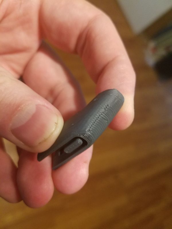
That being said the print came out much better, and now i am having blobbing which if i am not mistaken can be tuned out with pressure advance, as I have no stringing on non-printing moves between pieces or between movements on the same piece, pics included for reference.
The focus was off on a couple of them but you can still see what i am referring to.
-
David I was thinking about Jerk values reading someone's ideas with z sensors and they probe with jerk values set to 0. Can you see anything wrong with doing that? Surely all that means is the axis has to accelerate smoothly from 0mm/s on any movement?
Yes, that should work. If you are trying to avoid false triggering at the start of a probing move, another way is to use the MOD signal from the Z probe connector to arm the probe electronics.
Thinking about it, it may make sense for me to change the firmware to use zero jerk during bed probing anyway.
-
Ooo that's sound like a good idea David
-
I'm interested to know more about the MOD signal.
In theory with our board it doesn't need to be powered unless probing, although I do find it useful to watch the LED (as I always did with FSR's) to see how the nozzle is "riding" over the previous layer.
False triggers are not a big problem. Certainly easily managed with reduced jerk, possibly with reduced acceleration also.
-
When you select probe type 5 in the M558 command, the MOD signal is normally LOW but is driven HIGH at the start of a probing move and goes LOW again when the probing move completes.
I checked the code, and bed probing moves are already executed with zero jerk. If your printer allows a very high Z acceleration, there might be some merit in reducing it during probing.