Endstop on 2nd Y motor
-
I am configuring my new Maestro for my dedicated laser machine.
My table has a dual Y axis and I want independant homing. In RRF3 it is said that I do not need to configure a U axis and hide it, like it was previously.This is what I did:
; Drives
M569 P0 S0                                         ; physical drive 0 goes backwards
M569 P1 S0                                         ; physical drive 1 goes backwards
M569 P2 S0                                         ; physical drive 2 goes backwards
M569 P3 S1                                         ; physical drive 3 goes forwards
M569 P4 S0                                         ; physical drive 4 goes backwards  /  2nd Y motor
M584 X0 Y1:4 Z2 E3 P3                      ; set drive mapping  /  map 2nd Y motor to Y axis

; Endstops
M574 X1 S1 P"xstop"                         ; configure active-high endstop for low end on X via pin xstop
M574 Y1 S1 P"ystop+e1stop"                  ; configure active-high endstop for low end on Y via pin ystop
M574 Z2 S1 P"zstop"                         ; configure active-high endstop for low end on Z via pin zstop
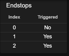
DWC does not show the status of the second Y endstop:

And also M119 does not give any info on that endstop status.
What am I doing wrong?
Thanks! -
DWC and M119 will show the Y endstop as triggered if either switch is triggered. So you can test them by triggering one at a time. When you home Y, each switch will stop its own motor.
-
@dc42 said in Endstop on 2nd Y motor:
... When you home Y, each switch will stop its own motor.
Okay, so in M574 the endstops pins must be defined in the order the motors were assigend in the M584. That seems an obvious thing to do, but I did not realise they would show up as one "virtual" endstop. I wil try. First I need to recrimp my endstop cables. In the factory ones I have most pins seem to make no contact...
Thanks!