G29 Warning: Skipping grid point
-
Hello
i have a Problem with the Mesh Compensation.
Something is wrong. I already had that with my old Duet wifi.Warning: Skipping grid point (45.0, -135.0) because Z probe cannot reach it Warning: Skipping grid point (0.0, -135.0) because Z probe cannot reach it Warning: Skipping grid point (-45.0, -135.0) because Z probe cannot reach it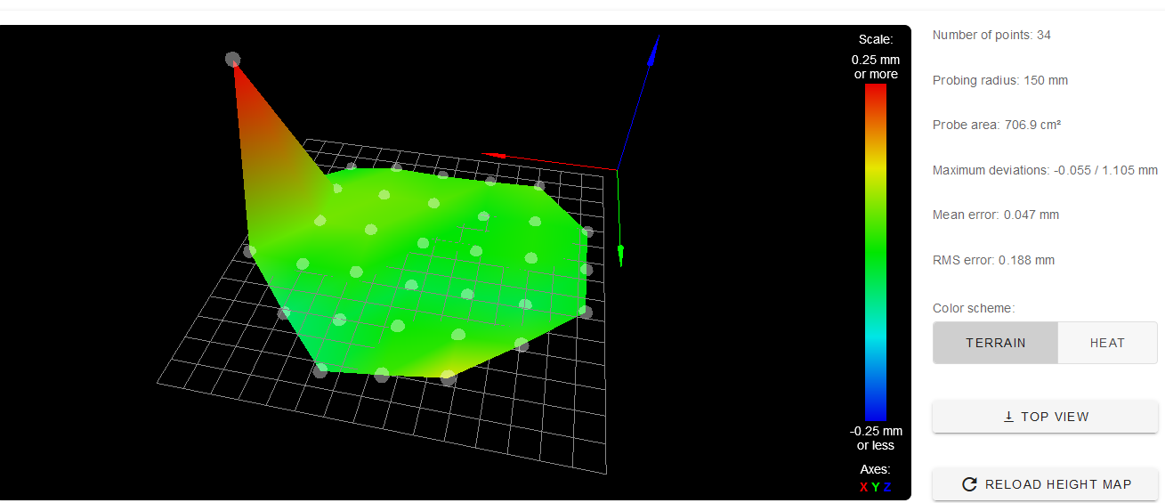
Otherwise it looks good.
Printer Delta Tevo Little Monster.
; bed.g
; called to perform automatic delta calibration via G32
;
; generated by RepRapFirmware Configuration Tool v3.1.4 on Mon Jul 27 2020 00:52:15 GMT+0200 (Mitteleuropäische Sommerzeit)
M561 ; clear any bed transform
G28  ; home all towers
; Probe the bed at 6 peripheral and 6 halfway points, and perform 6-factor auto compensation
; Before running this, you should have set up your Z-probe trigger height to suit your build, in the G31 command in config.g.
G30 P0 X0 Y132.28 H0 Z-99999
G30 P1 X121 Y69.86 H0 Z-99999
G30 P2 X129.9 Y-75 H0 Z-99999
G30 P3 X0 Y-150 H0 Z-99999
G30 P4 X-129.9 Y-75 H0 Z-99999
G30 P5 X-121 Y69.86 H0 Z-99999
G30 P6 X0 Y59.15 H0 Z-99999
G30 P7 X56.09 Y32.38 H0 Z-99999
G30 P8 X64.95 Y-37.5 H0 Z-99999
G30 P9 X0 Y-75 H0 Z-99999
G30 P10 X-64.95 Y-37.5 H0 Z-99999
G30 P11 X-56.09 Y32.38 H0 Z-99999
G30 P12 X0 Y0 H0 Z-99999 S6
; Use S-1 for measurements only, without calculations. Use S4 for endstop heights and Z-height only. Use S6 for full 6 factors
; If your Z probe has significantly different trigger heights depending on XY position, adjust the H parameters in the G30 commands accordingly. The value of each H parameter should be (trigger height at that XY position) - (trigger height at centre of bed)
G29
; General preferences G90 ; send absolute coordinates... M83 ; ...but relative extruder moves M550 P"Duet 3" ; set printer name M665 R155 L397.19 B155 H508 ; Set delta radius, diagonal rod length, printable radius and homed height M666 X0 Y0 Z0 ; put your endstop adjustments here, or let auto calibration find them; config-override.g file generated in response to M500 at 2020-07-29 17:23 ; Delta parameters M665 L397.190:397.190:397.190 R155.000 H508.000 B155.0 X0.000 Y0.000 Z0.000 M666 X0.000 Y0.000 Z0.000 A0.00 B0.00 ; Heater model parameters M307 H0 A141.1 C510.5 D4.3 S1.0 V23.7 B0 M307 H1 A582.2 C173.6 D4.1 S1.0 V23.4 B0 ; Workplace coordinates G10 L2 P1 X0.00 Y0.00 Z0.00 G10 L2 P2 X0.00 Y0.00 Z0.00 G10 L2 P3 X0.00 Y0.00 Z0.00 G10 L2 P4 X0.00 Y0.00 Z0.00 G10 L2 P5 X0.00 Y0.00 Z0.00 G10 L2 P6 X0.00 Y0.00 Z0.00 G10 L2 P7 X0.00 Y0.00 Z0.00 G10 L2 P8 X0.00 Y0.00 Z0.00 G10 L2 P9 X0.00 Y0.00 Z0.00; Configuration file for Duet 3 (firmware version 3) ; executed by the firmware on start-up ; ; generated by RepRapFirmware Configuration Tool v3.1.4 on Mon Jul 27 2020 00:52:15 GMT+0200 (Mitteleuropäische Sommerzeit) ; General preferences G90 ; send absolute coordinates... M83 ; ...but relative extruder moves M550 P"Duet 3" ; set printer name M665 R155 L397.19 B155 H508 ; Set delta radius, diagonal rod length, printable radius and homed height M666 X0 Y0 Z0 ; put your endstop adjustments here, or let auto calibration find them ; Drives M569 P0.0 S1 ; physical drive 0.0 goes forwards M569 P0.1 S1 ; physical drive 0.1 goes forwards M569 P0.2 S1 ; physical drive 0.2 goes forwards M569 P0.3 S1 ; physical drive 0.3 goes forwards M584 X0.0 Y0.1 Z0.2 E0.3 ; set drive mapping M350 X16 Y16 Z16 E16 I1 ; configure microstepping with interpolation M92 X160.00 Y160.00 Z160.00 E403.00 ; set steps per mm M566 X1200.00 Y1200.00 Z1200.00 E1200.00 ; set maximum instantaneous speed changes (mm/min) M203 X18000.00 Y18000.00 Z18000.00 E1200.00 ; set maximum speeds (mm/min) M201 X1000.00 Y1000.00 Z1000.00 E1000.00 ; set accelerations (mm/s^2) M906 X1200 Y1200 Z1200 E1200 I30 ; set motor currents (mA) and motor idle factor in per cent M84 S30 ; Set idle timeout ; Axis Limits M208 Z0 S1 ; set minimum Z ; Endstops M574 X2 S1 P"io1.in" ; configure active-high endstop for high end on X via pin io1.in M574 Y2 S1 P"io2.in" ; configure active-high endstop for high end on Y via pin io2.in M574 Z2 S1 P"io3.in" ; configure active-high endstop for high end on Z via pin io3.in ; Z-Probe M950 S0 C"io4.out" ; create servo pin 0 for BLTouch M558 P9 C"^io4.in" H5 F120 T6000 ; set Z probe type to bltouch and the dive height + speeds G31 P25 X0 Y20 Z0.35 ; set Z probe trigger value, offset and trigger height alt P500 testen M557 R150 S45 ; define mesh grid ; Heaters M308 S0 P"temp0" Y"thermistor" T100000 B4138 ; configure sensor 0 as thermistor on pin temp0 M950 H0 C"out0" T0 ; create bed heater output on out0 and map it to sensor 0 M307 H0 B1 S1.00 ; enable bang-bang mode for the bed heater and set PWM limit M140 H0 ; map heated bed to heater 0 M143 H0 S120 ; set temperature limit for heater 0 to 120C M308 S1 P"temp1" Y"thermistor" T100000 B4138 ; configure sensor 1 as thermistor on pin temp1 M950 H1 C"out1" T1 ; create nozzle heater output on out1 and map it to sensor 1 M307 H1 B0 S1.00 ; disable bang-bang mode for heater and set PWM limit ; Fans M950 F0 C"out4" Q500 ; create fan 0 on pin out4 and set its frequency M106 P0 S0 H-1 ; set fan 0 value. Thermostatic control is turned off ; Tools M563 P0 D0 H1 F0 ; define tool 0 G10 P0 X0 Y0 Z0 ; set tool 0 axis offsets G10 P0 R0 S0 ; set initial tool 0 active and standby temperatures to 0C ; Custom settings are not defined ; Miscellaneous M575 P1 S1 B57600 ; enable support for PanelDue M911 S10 R11 P"M913 X0 Y0 G91 M83 G1 Z3 E-5 F1000" ; set voltage thresholds and actions to run on power loss M501 -
Hi,
Did you try generating a new set of G30 commands using a smaller probe radius?
Frederick
-
This post is deleted! -
Ok i will test it.
-
120 mm works.
But why the other size not work ? I have a size of D340 mm -
134 also still works.
-
Hi,
Did you take into account the 20mm Y offset of the probe?
You might find this interesting to be sure you are not setting the printable radius value too large.
Frederick
-
@roth said in G29 Warning: Skipping grid point:
G31 P25 X0 Y20 Z0.35
The offset of the probe from the nozzle means that the probe can't physically reach some of the points requested in the M557 command. You can see the edge of the circle being cut off in your heightmap display.
Reducing the entire radius is one option so that all points are within reach, but you could also just leave the radius the same and accept that some points are not reach.
It's easier to configure a square grid to maximize the available probable area than it is with a radius.