Raise3D N2 with Duet Wifi
-
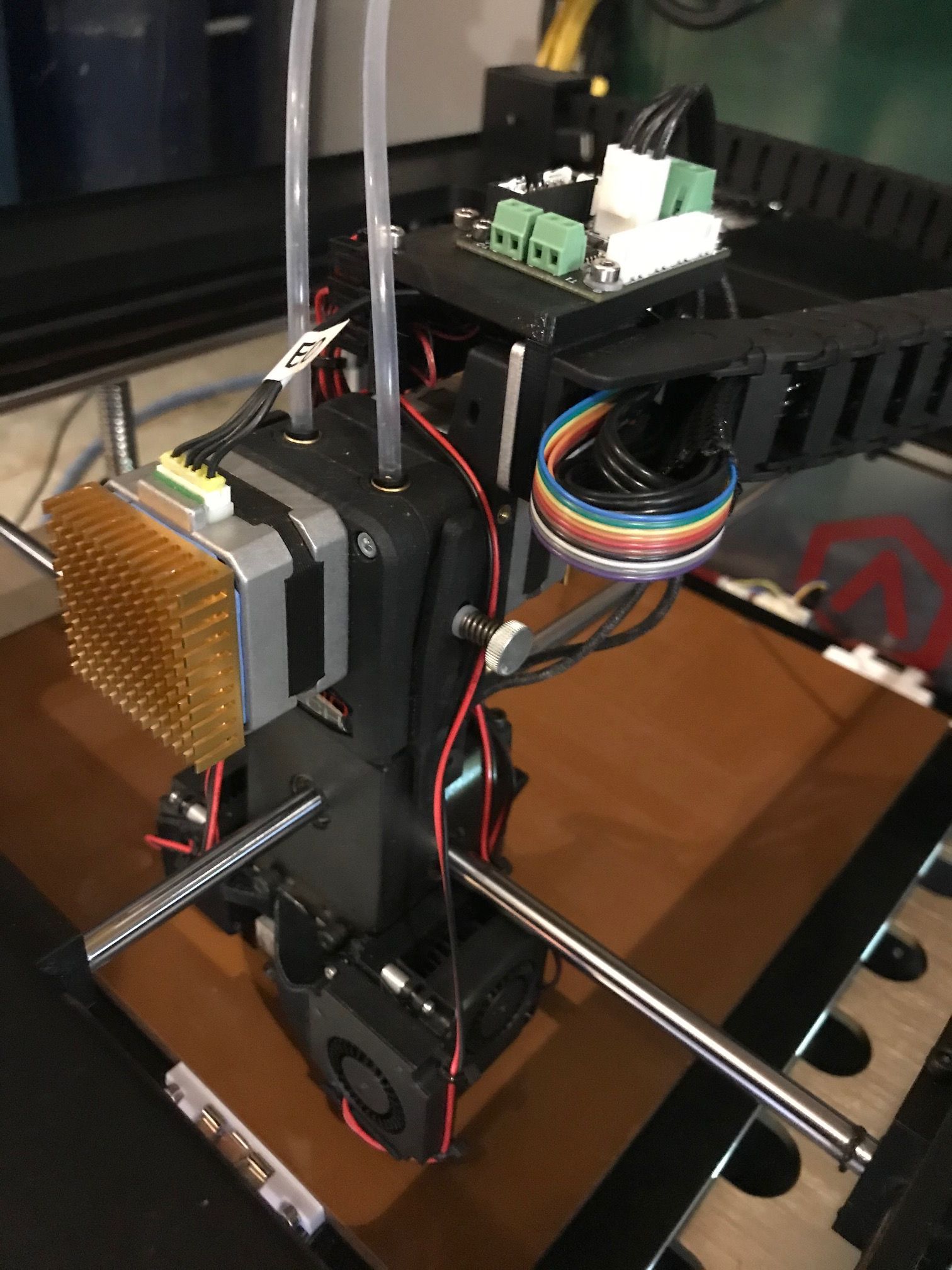
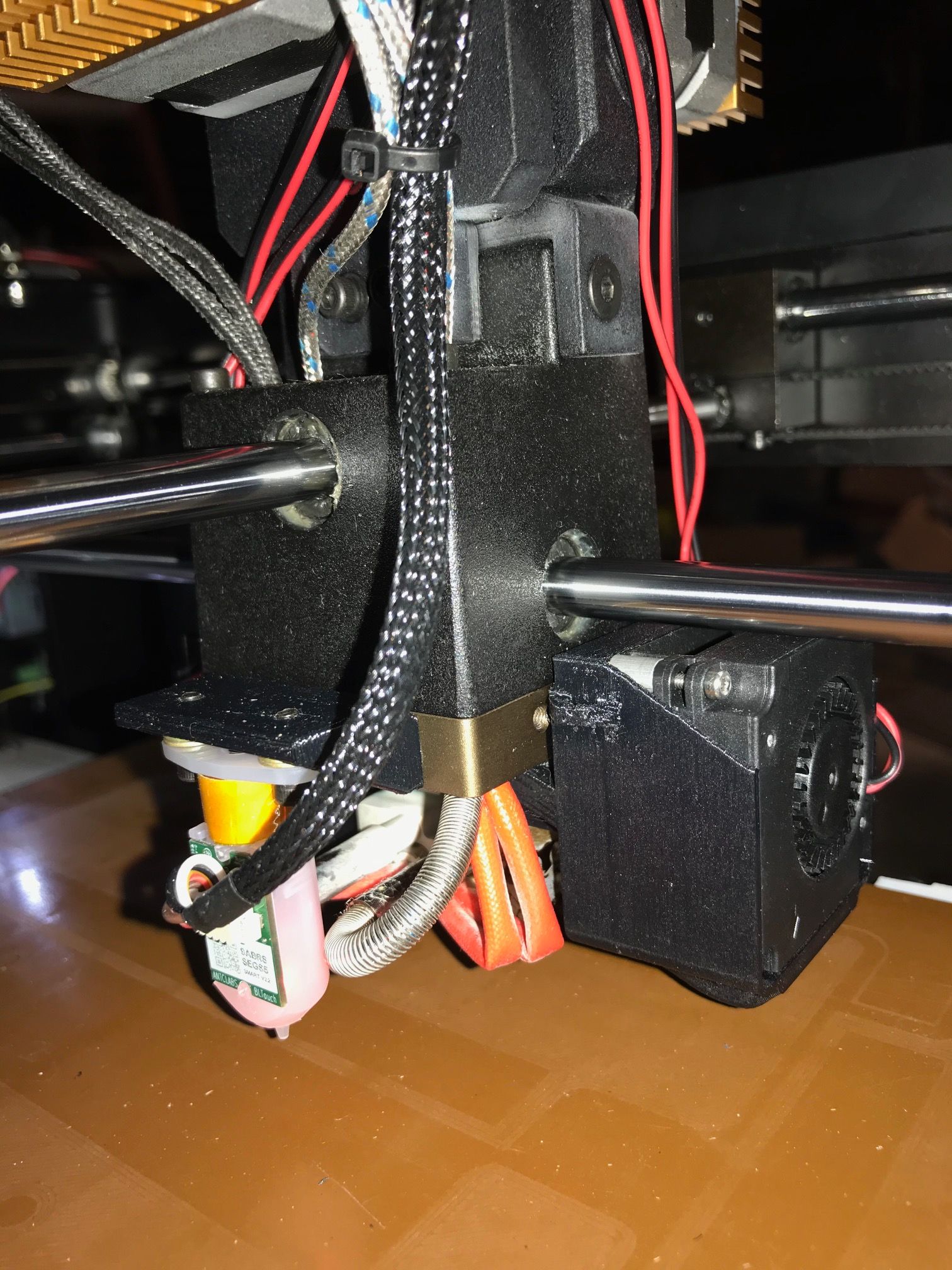
I recently upgraded my Raise3D N2 to a Duet 2 Wifi. I'm using both PT100 and thermocouple daughterboards. The PT100 board is for the bed sensor - could not use the stock sensor. The hot ends use thermocouples. I mounted the thermocouple board on the print head so I didn't need to run thermocouple wire down to the control board.
I added a BL Touch.I kept the factory daughterboard on the print head, but I'm only using it for the heater terminal blocks. I didn't have a better option in the parts bin.
The machine has also been modified to have a heated enclosure on an independent temperature controller. The bed has been modified to to get the clips out of the build area and make it easier to use alternative bed materials. It has the bondtech dual extruder upgrade.
The print head has additional fans for improved cold-end cooling and controllable print cooling.
All the 3D printed parts in the photos have been replaced with new prints since the upgrade since I'm getting much better results from the machine with the Duet board.

Heaters and fans for the heated enclosure.

I also have the 12x12x24" N2+ - that will get the Duet treatment soon.
-
I have since learned that having a long extension cable from the Duet to the Thermocouple daughterboard is a bad idea. I guess I've been lucky with the N2 with about 6ft of ribbon cable. Did have one thermocouple that "went bad" - replacing the thermocouple resolved the issue, but I now think it was a communication issue.
I have the N2+ wired up the same way, but due to the additional height it needs more ribbon cable, and neither of the extruder thermocouples is reporting reliably. Found some shielded thermocouple wire on eBay that will let me move the thermocouple board down to the Duet board.
Sucks that I have to cut all the wiring loose from the print head and route it all again - thought I was done with this project. I don't have good connectors for the thermocouples, but I plan to mount the Raise daughterboard back in its original location. I'll use the thermocouple terminals on that to connect the thermocouples to the long leads. I'll cut through the traces coming off those terminals to ensure the circuits on the board don't cause trouble. Hope that will get the job done.
-
I know very little about the Raise 3D printers. However, the wire between the thermocouple and the device that reads it should always be twisted pair, and made from the same materials as the thermocouple itself. Most K-type thermocouples (the type generally used in 3D printers) have long green/white twisted pair wires.
Duet WiFi hardware designer and firmware engineer
Please do not ask me for Duet support via PM or email, use the forum
http://www.escher3d.com, https://miscsolutions.wordpress.com -
@dc42 Thank you. I am familiar with thermocouples and the need to avoid dissimilar materials (thus creating another thermocouple junction).
I have found multiple posts stating the Raise3D thermocouples are type K, although the leads from them are Red/White or Red/Black rather than Green/White.
The wire I purchased on eBay is twisted and shielded type K wire, stranded 24 gauge - so hopefully it will survive the flex of the cable chain (not severe). I'll connect the shield to a ground connection on the board.
-
@dc42 A few nights back I moved the thermocouple daughterboard down to the Duet2 Wifi board. I cut all the traces around the terminal blocks on the Raise daughterboard where the thermocouples used to connect. I checked resistance between all the terminals to ensure they are completely disconnected and isolated from the circuitry on the Raise board - so I'm just using the terminal blocks to clamp the thermocouple wires together at the print head.
To ensure I'm getting the thermocouple wires clamped directly together, they are twisted before going into the terminal block clamp.
The twisted and shielded thermocouple leads are about 8' long between the print head and the Duet3D board. The shield drain leads go do a vacant ground pin on an extruder end-stop connector.
I have an RT100 board on the main board. The thermocouple board stacks on top of the RT100 board.
When I power up the machine the RT100 reads correctly and both channels of the thermocouple board show faults (Red LED) and read 2000.
I checked that everything is fully seated. In the process, I touched a finger to the open pins on the top of the thermocouple board and the fault lights went off. Temps appear to report correctly.
I found a post where you suggested adding .01uf capacitors to the thermocouple board to help filter noise. I added those tonight, but the issue persists.
I tried removing the thermocouple wires from the Raise3D daughterboard terminals to see if it was something about making the connections in those terminals. That doesn't eliminate the error.
I haven't identified exactly which pins need to be touched to clear the error. Seems to one or both of the first pair inboard to the center pins.
Any thoughts?
UPDATE: - my knowledge of digital electronics is somewhere on the low end of "enough to be dangerous" ... thinking that my touch may be just a bit of resistance between pins, I took a piece of ESD foam from a CPU chip package (it is slightly conductive) and pushed it on to the open pins of the TC board. That doesn't clear the fault. If I touch the foam, however, it clears the fault. I tried touching a grounded wire to the foam and that didn't do anything.
-
This post is deleted! -
Hello! I have a N2+ that I converted to a Duet 2 Wifi as well but am having difficulty with the configuration. Any chance you could share what you setup or give me some tips? One of my main problems is a reversing axis.
-
@rayman said in Raise3D N2 with Duet Wifi:
Hello! I have a N2+ that I converted to a Duet 2 Wifi as well but am having difficulty with the configuration. Any chance you could share what you setup or give me some tips? One of my main problems is a reversing axis.
Do you mean an axis is running backwards, or the direction reversing? You can reverse an axis with the S parameter on the M569 command. If it's changing direction when it shouldn't be, that's probably a wiring issue that not all leads are properly connected.
Here is my current config.g. I have a BL-Touch as the Z-stop and bed meshing which is wired like this: https://forum.duet3d.com/topic/7972/bl-touch-install-success
I run the Bondtech extruder and have removed all of the second extruder bits to reduce weight as I only run one material.I replaced the thermocouples in the hot-end with E3D thermisters. I added a PT100 temp sensor to the bed.
; Configuration file for Duet WiFi (firmware version 3)
; executed by the firmware on start-up
;
; generated by RepRapFirmware Configuration Tool v3.1.10 on Fri Dec 11 2020 19:17:48 GMT-0500 (Eastern Standard Time)

; General preferences
G90                                                ; send absolute coordinates...
M83                                                ; ...but relative extruder moves
M550 P"N2A"                                        ; set printer name

; Network
M552 S1                                            ; enable network
M586 P0 S1                                         ; enable HTTP
M586 P1 S0                                         ; disable FTP
M586 P2 S0                                         ; disable Telnet

; Drives
M569 P0 S0                                         ; physical drive 0 goes backwards
M569 P1 S0                                         ; physical drive 1 goes backwards
M569 P2 S1                                         ; physical drive 2 goes forwards
M569 P3 S1                                         ; physical drive 3 goes forwards
M584 X0 Y1 Z2 E3                                 ; set drive mapping

;Microstepping 64
M350 X64 Y64 Z64 E64 I1                         ; configure microstepping with interpolation
M92 X320 Y320 Z3200 E1660                      ; set steps per mm 1660 theoretical

M566 X400 Y400 Z100 E400                       ; set maximum instantaneous speed changes (mm/min)
M203 X24000 Y24000 Z1200 E1200                ; set maximum speeds (mm/min)
M201 X2000 Y2000 Z250 E25000                 ; set accelerations (mm/s^2)
M906 X900 Y900 Z900 E800 I30                   ; set motor currents (mA) and motor idle factor in per cent
M84 S30                                            ; Set idle timeout

; Axis Limits
M208 X0 Y-13 Z0 S1                                 ; set axis minima
M208 X305 Y305 Z305 S0                             ; set axis maxima

; Endstops
M574 X1 S1 P"!xstop"                                ; configure active-high endstop for low end on X via pin xstop
M574 Y1 S1 P"!ystop"                                ; configure active-high endstop for low end on Y via pin ystop
M574 Z1 S2                                          ; configure Z-probe endstop for low end on Z

; Z-Probe
M950 S0 C"exp.heater3"                             ; create servo pin 0 for BLTouch
M558 P9 C"^zprobe.in" H2 F60:30 T24000             ; set Z probe type to bltouch and the dive height + speeds
G31 P25 X12.5 Y51.05 Z3.5                          ; set Z probe trigger value, offset and trigger height
M557 X25:275 Y50:300 S50 	   ; define mesh grid
M307 H3 A-1 C-1 D-1

; Heaters
M308 S0 P"spi.cs1" Y"rtd-max31865"                 ; configure sensor 0 as RTD on pin spi.cs1
M950 H0 C"bedheat" T0                              ; create bed heater output on bedheat and map it to sensor 0
M307 H0 B1 S1.00                                   ; enable bang-bang mode for heater
M143 H0 S120                                       ; set temperature limit for heater 1 to 120c
M140 H0                                            ; map heated bed to heater 0
M143 H0 S120                                       ; set temperature limit for heater 0 to 120C
M308 S1 P"e0temp" A"Tool 0" Y"thermistor" T100000 B4092 ; sensor 1
M950 H1 C"e0heat" T1 ; create heater and map sensor 1

M307 H1 B0 S1.00                                   ; disable bang-bang mode for heater  and set PWM limit
M143 H1 S310                                       ; set temperature limit for heater 1 to 310C
M308 S4 Y"mcu-temp" A"MCU"                         ; configure sensor 4 as MCU temp


; Fans
M950 F0 C"fan0" Q500                               ; create fan 0 on pin fan0 and set its frequency
M106 P0 S0 H-1                                     ; set fan 0 value. Thermostatic control is turned off
M950 F1 C"fan1" Q500                               ; create fan 1 on pin fan1 and set its frequency
M106 P1 S1 H1 T40                                ; set fan 1 value. Thermostatic control is turned on
M950 F2 C"fan2" Q20                               ; create fan 2 on pin fan2 and set its frequency
M106 P2 H4 L128 X255 B0.3 T40:60                   ; set fan 2 value

; Tools
M563 P0 D0 H1 F0                                   ; define tool 0
G10 P0 X0 Y0 Z0                                    ; set tool 0 axis offsets
G10 P0 R0 S0                                       ; set initial tool 0 active and standby temperatures to 0C

; Custom settings are not defined
M591 D0 P1 C"e1_stop" S1	       	        	   ; filament runout sensor EXT 0, Low=Filament Present, endstop 1

; Miscellaneous
M501                                               ; load saved parameters from non-volatile memory
M911 S10 R11 P"M913 X0 Y0 G91 M83 G1 Z3 E-5 F1000" ; set voltage thresholds and actions to run on power loss