Indirect Laser Filament Monitor Build
-
I saw this really cool indirect laser filament monitor design on thingaverse and I wanted to build it.
I have all of my pictures on this website of the build:
https://www.randoprojects.com/2020/08/15/indirect-laser-filament-monitor/Printer: Ender 5 w/ Hemera Direct Drive
I got very accurate results for periods of time and then others it was just as bad as the traditional direct. I have determined that the carbon fiber is a great medium and the laser picks it up well but the current design doesn't feed the filament straight through so depending on the position of the Hemera it could slip.
I don't have a CAD system to modify the design. I do think with a mod to add bowden coupler on the output in addition to either a bowden coupler or a a microswitch system on the input side, the feed issue would be resolved and the sensor would be more accurate. It seems the natural curve of the filament can slip on the pulley at certain angles which change as the direct drive moves around.

Question:
When using an indirect sensor approach with the laser the percentage of error will be reported wrong due the the size of the shaft and the extruder pulley being different. I am curious, can the laser sensor be used as a rotating sensor so the L parameter can be used for a correction value?Has anyone had good luck with improving performance and consistency with other indirect solutions?
-
Image of the carbon fiber shaft.

Image of the mounted PCB

I am thinking perhaps a hobbed version of the shaft pulley would be better such as this one:
https://amzn.to/2Ed1QezInstead of the idler pulley this type of microswitch has a short lever arm and more pressure is required. This could serve as both the idler pulley and the filament out microswitch:
https://amzn.to/3asXKeBAnother option would be to sandwich the filament between two hobbed pulleys that are connected by a gear:
https://amzn.to/3iMtoXnTrying to decide if/when to give up on the laser and go to the hall effect style rotating sensor. Thoughts?
-
I have ordered the rotating mag filament monitor but I would still like to see if this laser monitor can be salvaged. I would also really like to see if a small micro switch could be added for the static filament present state.
I am not great at CAD but this would be the difference.
- Get rid of the spring and idler pulley
- Use a geared MK3 style dual extruder
- A support at the top and bottom to keep the filament straight and reduce slips due to the filament curve
- Add a micro switch inline (normally open)
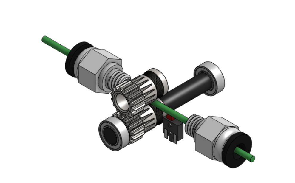
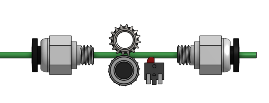
The top gear would use a linear bearing and a stationary 3mm axle based on this assembly:
https://amzn.to/3hpxzbsI could provide the stp file if anyone knows how one might create the enclosure around this concept?