Robotic kinematics
-
ok! I'm sorry but I'm the one sending you into confusion, I explain myself badly. (simulation) if I turn on the 5 axis robot based on the M669 K13 X20.0: 5.0 Y0.0: 10.0 Z50.0 R1 L300.0: 400.0: 200.0: 100.0 P0 and A-45: 45: 0: 75: -75: -5: -170: 170: -135: 135 which is the configuration of your example I type M114 which positions of X, Y, Z.... would I see respond from duet? I would like to understand where the robot arm thinks it is before homing the 5 axes! I will start building the robot as soon as possible, surely as I did with scara in rrf I will encounter problems with the configuration I will ask you for help if you will be patient! thanks, see you soon!
-
@tony73 the problem with homing is, the starting position of the steppers is not known! The stepper rotates until the endstop is hit. So the robot must home in such a strategy that the different axes are homed with valid movements.
An alternative is to make sure the starting positions are near the endstops already, so for homing only a few small movements are necessary.
I thought about this also and had the idea that an external measuring system could give duet a hint about the current status, eg a camera image analysis.
Or always stop the robot at a known position at turn off and store that this procedure went well, so at startup duet can see whether it can start or should wait for user controlled moves into start position.
One more approach is to use absolute encoders, where the robot and duet always know where the axes are.
-
@tony73 good morning, now I am awake to answer your questions better!
M114 is a command to know the coordinates if the firmware already knows where the axes are. But as I explained in the previous comment, when you turn on the Duet, he doesn't know where it is. That's the reason for homing: rotate the steppers until it hits the axis movement with an endstop. You know where you installed the endstop, so you tell the firmware in the configuration where the endstop is, and the firmware can set the coordinates from this information. It is also possible to set the coordinates explicitly with G92.
Do you plan to use your robot for 3D printing, or build a new robot? If you want to use the exisiting one, you'll need to add the extruder/hotend part with arm 5. I am still thinking about how to construct axis 5 and arm 5 best. My plan is to split arm 5 into two parts to allow to make a tool changer.
-
Hello! you want to do a great job !! i thought it was a situation like scara when duet is turned on before homing thinks to be parallel to x axis with motor x 0 degrees approximately y 0 degrees with M114 responds with x398 and y0 because my scara with proximal arm 200 mm distal 200 mm . i tried to compile the firmware i had rrf 3.1.0 downloaded days ago when i got your help adding FiveAxisRobotKinematics.cpp and FiveAxisRobotKinematics.h taken from https://github.com/JoergS5/RepRapFirmware/tree/v3.02-dev/src/Movement/Kinematics
made step 4 fromhttps://github.com/Duet3D/RepRapFirmware/blob/dev/AddingNewKinematics.mdbut there are errors does not compile!
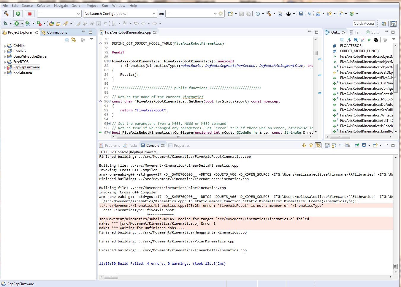
can you tell me where am I wrong? should i download a new rrf 3.1.0?
-
@tony73 this is step 4, adding the fiveAxisRobot to the Kinematics file, three places:
in Kinematics.cpp:
#include "FiveAxisRobotKinematics.h"then in the switch statement:
case KinematicsType::robot5axis:
return new FiveAxisRobotKinematics();and in Kinematics.h in the enum of KinematicsType:
robot5axis,David had renamed it from fiveAxisRobot to robot5axis, so I changed it also.
In the .h it must be at the correct position:
...
markForged,
collinearTriperon, // reserved...
robot5axis,
unknown // this one must be last!
}; -
ok! thanks I tried, successful compilation !!
-
@tony73 when you're ready with setup, please tell me your M669, then I can calculate whether all positions are calculated correctly (kinematics and inverse kinematics) - if you want.
PS to calculate errors exactly, I need steps/degree values of the actuators also (the M92 settings).
-
@JoergS5
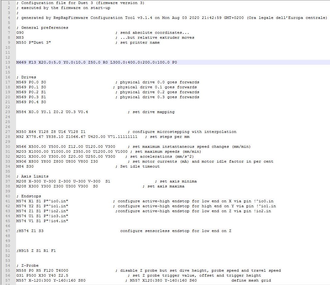
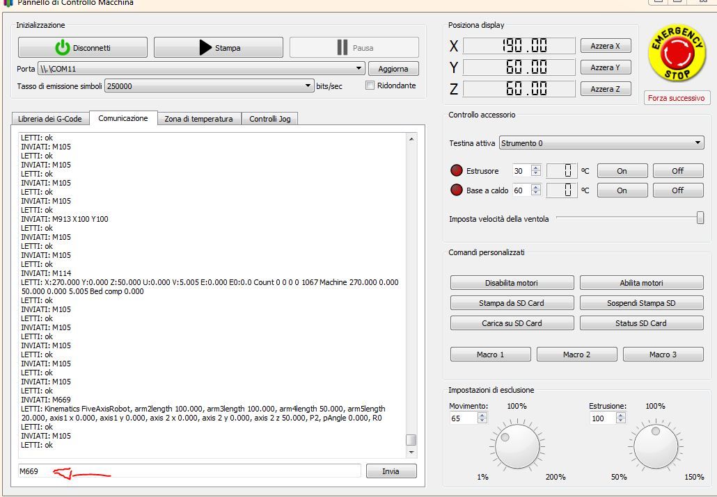
good morning ! i was trying duet 3 6ch with 5 stepper motors connected (one test) to see, in config .g gave M669 of your example M669 K13 X20.0: 5.0 Y0.0: 10.0 Z50.0 R0 L300.0: 400.0: 200.0 : 100.0 P0 but I changed R1 to R0 to have 5 stepper motors, duet 3 is connected to the pc with usb and simplify 3d. If I write M699 it responds like this
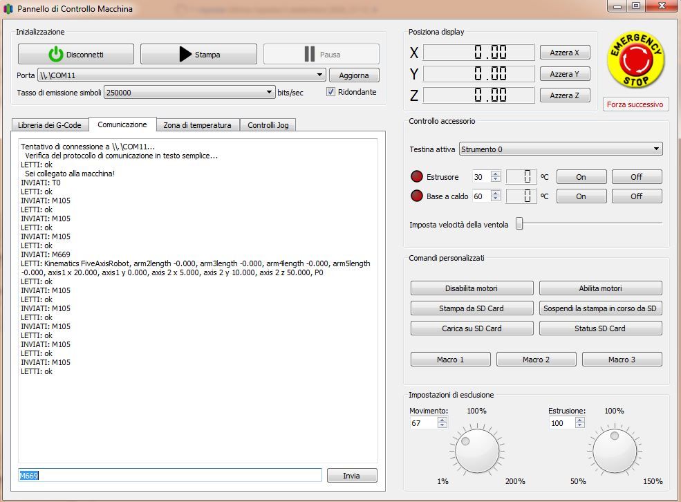
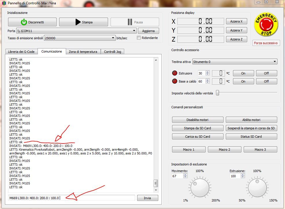
the lengths of the arms are missing and the parameter (R) if I write M669 L300.0: 400.0: 200.0: 100.0 accepts the arms but for (R0) nothing does not accept! what problem could that be?
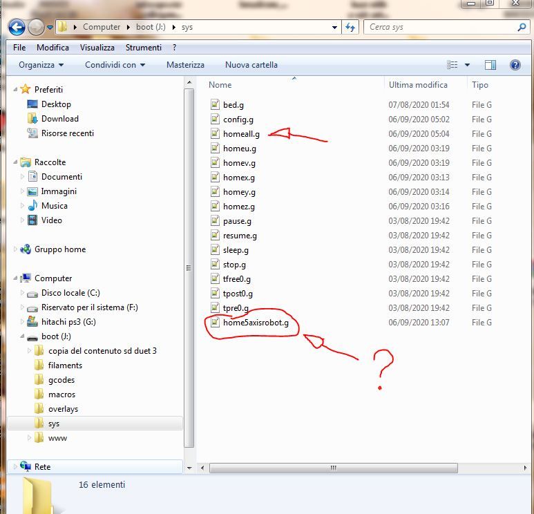
another thing is the total homing, it should be (home5axisrobot.g) but writing G28 does not accept only (homeall.g) or single axes, example (homex.g) , help !!!!
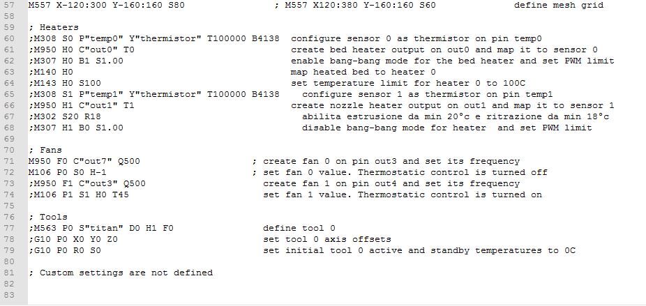
here is the (config.g) not very accurate fact, for a kidnapped test and little time available! Hello !!
-
@tony73 I cannot detect a bug in the source at the first view. Please let me some time, I can look at it the next days.
The homeall file is called home5axisrobot.g and homallg is not needed. This was a declaration in
static constexpr const char *Home5AxisRobotFileName = "home5axisrobot.g";
but I am not sure whether it is used correctly. I will check it also. -
I've used the term kinematics a number of times in this lecture and I haven't really been very clear about what it means. Kinematics is a branch of mathematics ...
-
@Antomy5 I don't know the definition, but I know what it means at 3D printers and robots: kinematics are functions of movement from actuators to the cartesian coordinates, and inverse kinematics is the other direction.
Kinematics in physics describe the motion of points or bodies, I think this is similar. -
OK !! you haven't tried to connect a duet card with homing motors and switches, to try it you can, at least see if the parameters type M669 respond (the various R0, R1, R2, P0, P1, P2: nnn, Lnnn: mmm: ppp: qqq, etc .... the parameter (R) seems to me to answer, but it is not seen when calling M669, home5axisrobot.g does not accept it, instead takes homeall.g, anyway thank you !!! and I wait !!!
-
@tony73 the reason why R0 is not visible is clear: I added it short time ago, it's not included in the status message yet. I'll add it.
I'll fix the other problems soon and tell you when I have a new source checked in in github. -
@tony73 Hello, I've found the errors and corrected them. I used a method which had unexpected side effects, so now I avoided it. The new release is checked in.
I changed the homefile name to homeall.g
Please feel free to report me if you find something else. I'll finish my prototype next, so I can test too (e.g. unusual arm movements).
-
Hello!! you were very fast, I recompiled the changes m669 looks ok! everything is visible
now i have to build a robot arm to try, i know the functions of the arms and the joints counterclockwise positive degrees clockwise negative degrees scara in this and similar, the problem remains that I don't understand this! the function !
I don't understand what to measure and how to build axis 1 and axis 2! what help does this parameter give you? you said you wanted flexibility, referring I believe the imperfections of the construction of the robot, thanks!
-
@JoergS5
ps . good morning! I re-read your help and I think I understand how it works (this feature)
can you just tell me if there is a limit of coordinates x, y, z ? can this be put?
M669 K13 X70.0: 70.0 Y70.0: 70.0 Z50.0 ......... -
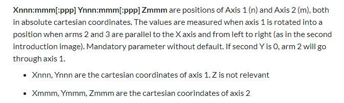
@tony73 you can simply build your robot as you like. You measure the properties of the robot after building the robot and set the parameters:
- measure arm lenghts 2 to 5
- measure where axis 1 and axis 2 are located and set parameters X, Y and Z according to the description (arms 2 and 3 parallel to x axis). Those coordinates are the places where you put the axes.
- measure and set the angles for all axes by homing or external measuring
Just build the robot, I will explain it better soon. From your questions I see that I did not explain it good enough. I will make it clearer with better images when I have a prototype my own and I can make images. The reason why I did not use images from the internet is, I wanted to avoid licensing problems.
-
good day! I saw that the updates continue! I found that if the size of the print bed (M208) is not right for the size of the robot arm, it won't move and write this (Error: G1 / G2 / G3: intermediate position outside machine limits). in (M208) should you put only X, Y, Z or also U, V?
Is parameter P1 working? can you give me an example how to change the angle of the 5th axis using P1?
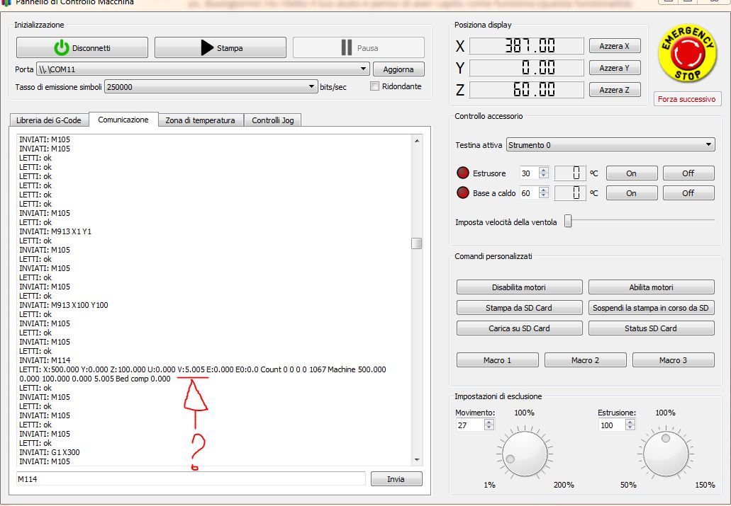
after homing the robot arm, before moving it, thinks it is stretched along the X axis with all the motors in 0 degree position (is that right or am I wrong?)another question, this is M114 immediately after homing, why does V always mark V 5.005? shouldn't it be zero? in M669 I put (P2: 0.0) thanks!
-
This post is deleted! -
This post is deleted!