Robotic kinematics
-
OK! eclipse firmware reloaded works! I would like to start building a robot that looks like this
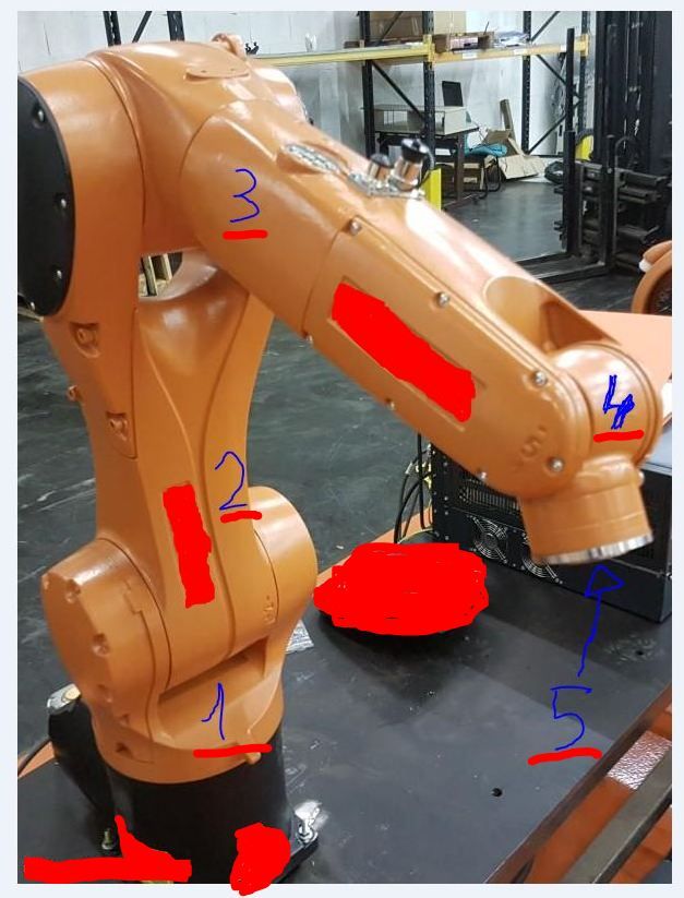
with example link 1 /150mm, link 2/ 200mm, link 3/ 200mm, link 4/ 100mm, link 5/ 80mm
the (link 4 could be 100mm? considering that I don't know if link 2 can go to less than 0 degrees (type arm 2 max 75 degrees min -45 degrees? and could you say reduction ratio would serve on the basis of these arms, for the 5 engines?maybe I made a wrong speech!
if link 1 is 150mm, I can make link 4 of 100mm that is 50mm less than link 1, can there be a problem or can it be done? can create problems at link 2 for min angle 0? -
@tony73 I think you confuse some of the distances, What you mark as link 1 distance has no meaning. Only how much it can rotate is important.
=> to answer your question, different axis lengths are no problem. Longer will probebly be more stable. I will use between 100 and 200 also.Link 2 min angle 0 is no problem. You must calibrate the angle at a different angle (eg 90 degree).
Your question according reduction ratio: which ratio do you plan?
At the 5 you must assemble something horizontal to hold a hotend if you want to use it for 3d printing.
The robot as such looks very stiff and will be precise (if the ratio is ok) imho. In axis 5 could be a harmonic drive. A planetoid gear could have backlash, but you could run it in P0 mode.Axis 1 is very important to be precise (exactly horizontal rotation eg), you should consider making the rotating plate as big/good/stiff as possible.
-
This post is deleted! -
@JoergS5
ok! I take note of all the advice! and thank you for your help! if these were the lengths of the robot arms ((X0.0: 0.0 Y0.0: 0.0 Z100.0 L200.0: 200.0: 100.0: 80.0)) what reduction ratio would you use so that the 5 motors have excellent precision?about the second robot you are building how long do you need to finish it?
-
@tony73 I don't exactly know the best ratio, the commercial robots often have 1:30 for every axis. My approach will be to calculate mathematically which is the best ratio:
high ratio means higher precision and more torque, but slower. So there will be an optimal ratio for the desired speed. Regarding the maximal extruder speed, the robot has a maximum speed. More speed (= low ratio) is not necessary and would result in lower precision. High ratio would be slow. The arm lengths are also important.To calculate is on my long todo list...
-
@tony73 said in Robotic kinematics:
about the second robot you are building how long do you need to finish it?
My recent firmware changes are the result of this building. The axis5offset (Xo, Yo) is to ease construction of axis 4 and 5. The main problem is axis 1. A few days left.
-
ok! could you write me what are the mandatory parameters from the last update, in M669?
Is the 5 axis offset a help for robot construction problems (I think accuracy) or is it about something else?
-
@tony73 The documentation is current, just use the sample at the end. The parameters which are not mentioned in the example are all optional or have a default value. P3 /P4 implementation is not finished.
The axis 4 must be exactly above axis 5. The axis5offset allows axis 5 to be outside this. This allows me to place axis 5 in front of arm 4. You'll see what I mean when I explain my construction. This is not documented yet (only the parameter, and it's already in the source and tested). Axis5offset has defaults 0.0/0.0.
-
I continue to follow your updates, thanks for the clarification and wait to see your robot!
-
@tony73 the robot you have shown could use a toolchanger at point 5 easily and should be a solid connection (like for CNC). But think about how to guide the wires and filament. I route it inside of the arms.
-
@tony73 I think I have understood M208 now after analyzing the firmware. The values are the axis values, not coordinates.
So M208 will have X, Y, Z, U, V values for the 5 axes and an optinal W value for a rail. Parameter A is not necessary any more then, I changed the source and documentation.I've made a little try with Openscad to illustrate axis5offset in the documentation.
-
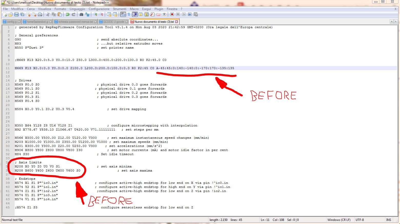
good morning! I reloaded the changes but as usual I don't understand how and where to put M208! I did some tests with M208 but I can no longer move the motors of the duet 3 only homing! have you tried with your robot to move it with these new parameters? my config.g was like this before
now I tried like this
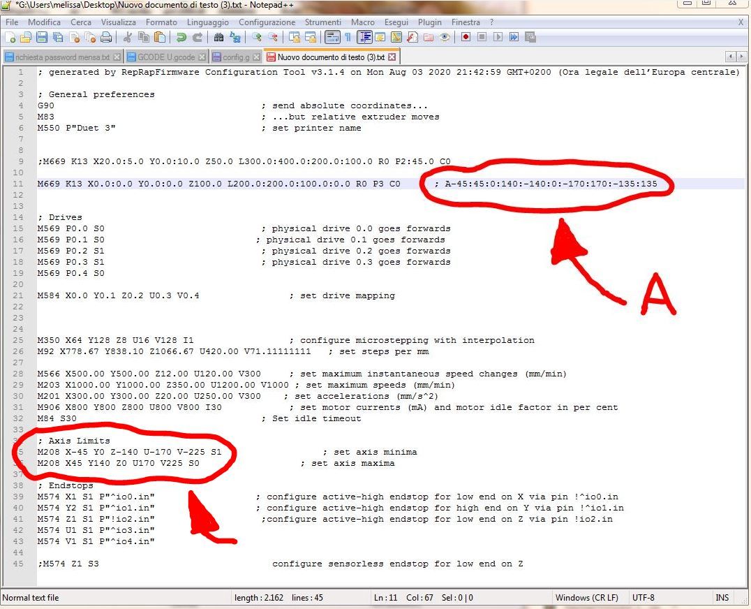
but that's not good! maybe it goes in M669 but how? but most importantly, are you trying the changes with the robot connected and moving? I ask you this to understand what I need to change!
-
@tony73 I'll check it tomorrow and tell you the result.
There is probably a bug in the code, your config is how it is meant.=> I found the bug, I'll correct and test it tomorrow.
-
I found that the motors move but it seems that the G1 commands are no longer Cartesian X Y movements but in degrees! if you send G1 X100 it does nothing but with G1 X30 it moves, like G1 Y55 moves. it moves on X Y Z U V but using the limits of degrees of M208 which are these
M208 X-45.0:45.0 Y0.0:140.0 Z-140.0:-0.0 U-170.0:170.0 V-225.0:225.0
-
@tony73 thanks a lot for the test, I've found the reason. I'll correct it and tell you when checked in.
The movements are not degrees, but for calculating the m208 restriction the original code is used (cartesian printer), this is wrong. -
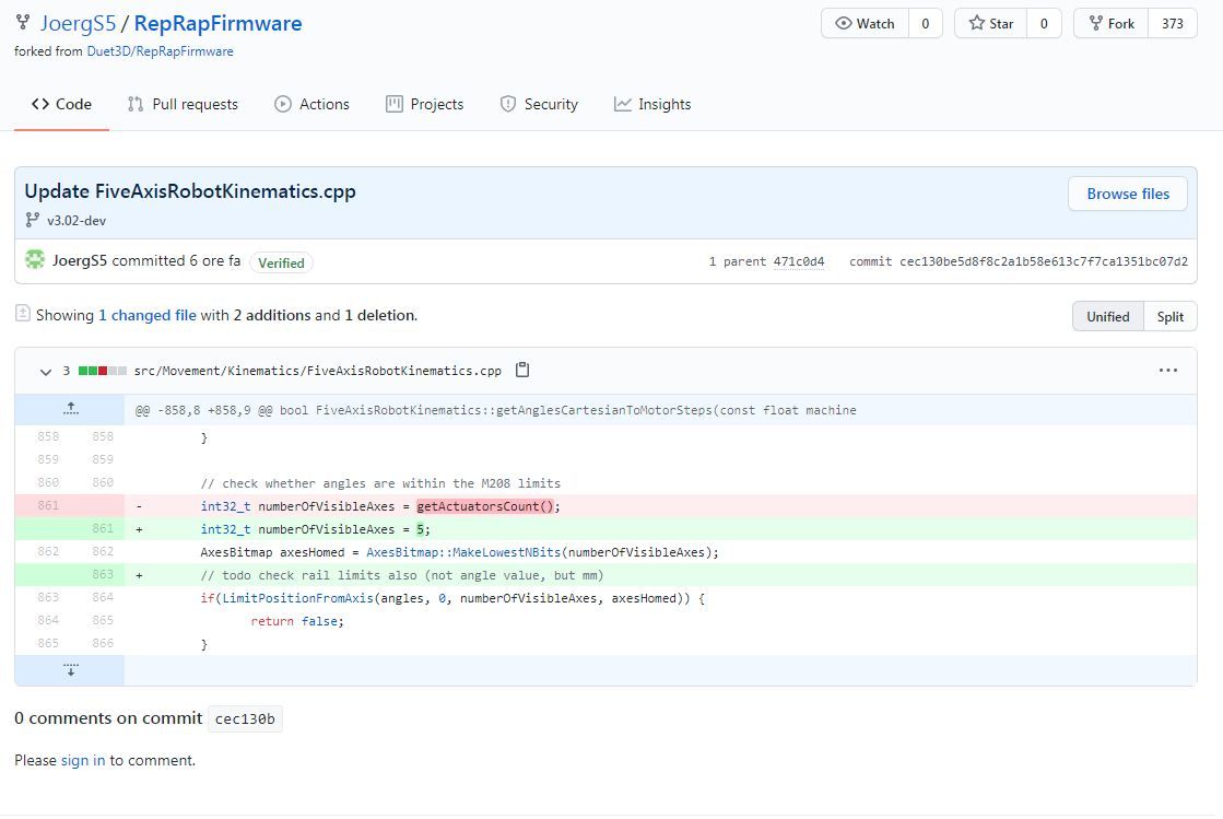
@tony73 I've corrected the M208 problem and checked in the code.
-
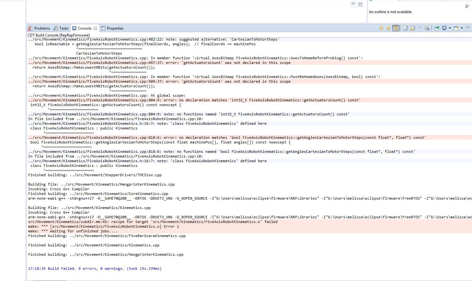
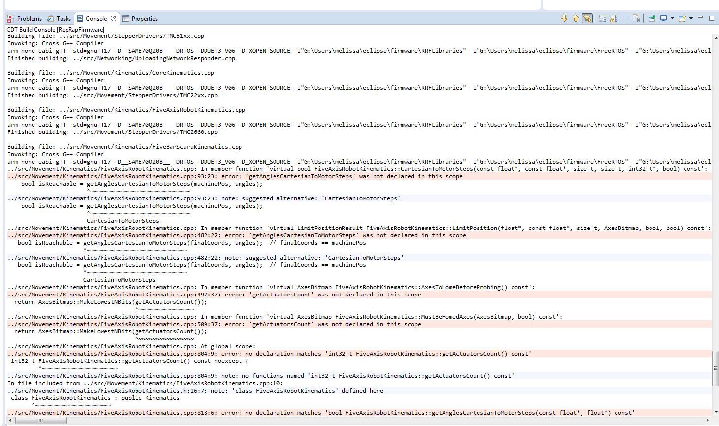
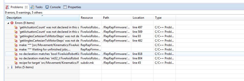
I tried to reload the code in eclipse it gives me errors, but it could be me that I am doing something wrong!
-
@tony73 grrr always this .h file....
I'll write me a postit to the display: "checkin both"!
Please try again.
-
i reloaded the firmware with the latest change in eclipse,
i left all parameters M669 as when i used A-45: 45: 0: 140: -140: 0: -170: 170: -135: 135 now i use M208 only change that o put P3 I was curious to see. I do everything as before homing G28 I write in simplify 3d G1 X300 but he replies that G1 / G2 / G3 are not enough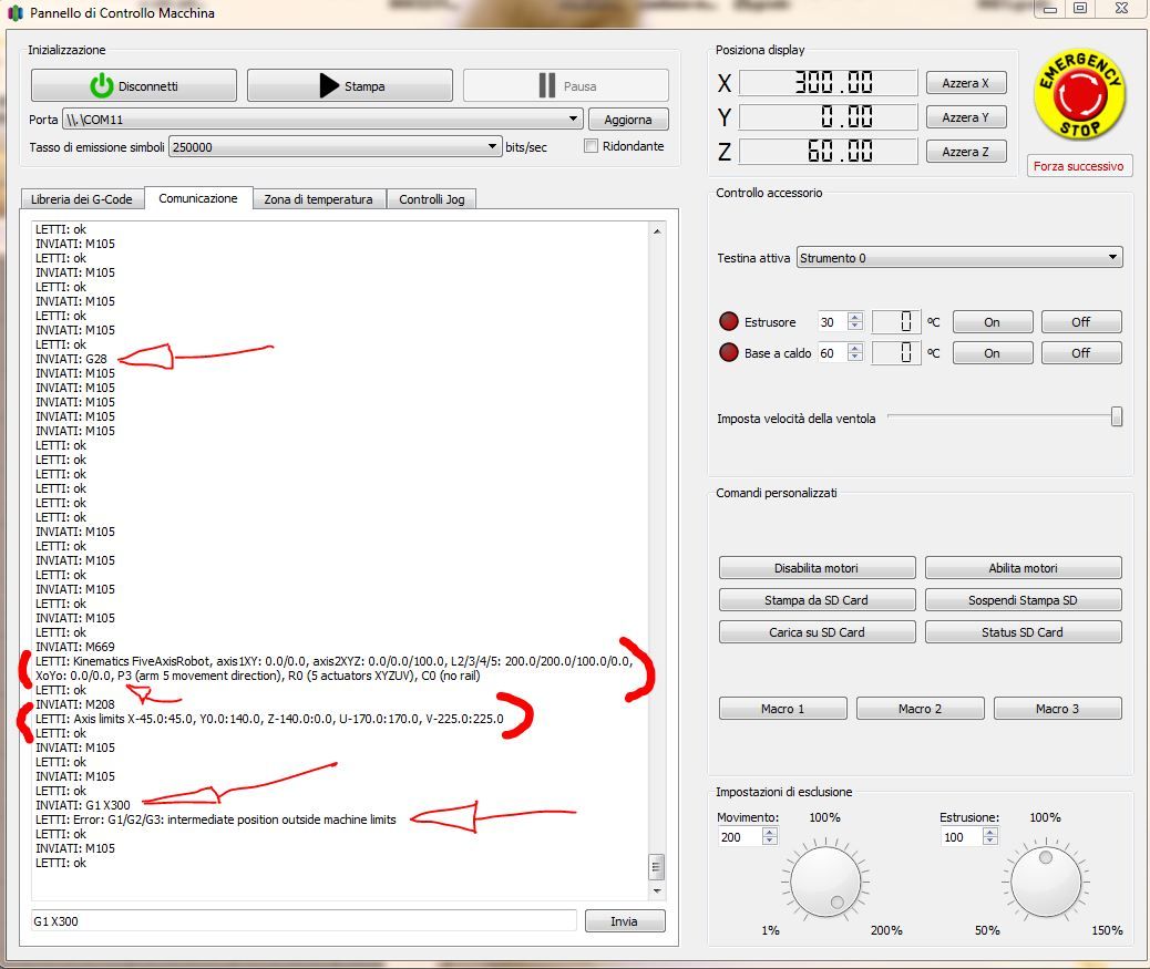
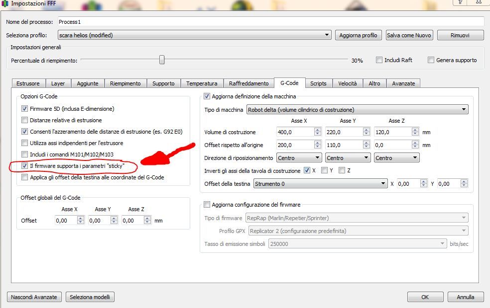
but I discovered that if I leave this parameter called STICKY active in simplify and start a print, the motors move, I stop the print, and it allows me to move the motors with G1 or G2 or G3 both in XY and Z, if I remove the STICKY parameter from simplify 3d, I start printing, nothing moves, all engines are stopped! maybe I set something wrong I don't know!
when I simulate the print with the STICKY parameter the motors move, first they make bad noises for about 5 seconds then they normalize !!
I also tried with P2: 45
same results !
-
@tony73 first idea is that your arm 5 length is 0, and I never tested it with length 0, so maybe there is an error in the code. I'll check tomorrow. (my assumption was that the hotend is never below arm 4 and must have a lenght).
G1 X300 should be reachable with arm 2 and 3 lengths of 200 each.
I'll try to extend the error message in the code, so it is more clear why firmware thinks that G1 is outside the machine limits.
I don't know sticky, what does it mean?
Could you please show your homing file, so I know what your axis values are after homing? Maybe an angle is wrong.*)
One more to check is where you are when you start the g1 x300 and whether its in absolute or relative move mode. Try a small move like g1 x20 first.
*) Please check the current positions with M114 and use absolute or relative mode G90 and G91 before the G1. (G91 G1 X20)
Your first screenshot about the source: actuator number changes with modes r0 r1 r2, but the m208 limit applies to all 5 angles always, thats why the change.