Bed mesh help please
-
hi i got my ir prob working but i have a wonky bed looks flat but its not how do i in-cress the bed mesh probing points
here's my macro for bed meshM557 X20:250 Y20:250 S40 ; Define a 6x4 point grid for measuring the bed
G28 Y ; Always home Y
G28 X ; Always home X
G28 Z ; Always home Z
G29 S0 ; Run probing sequence defined by M557 above S0 parameter saves the height map in a file on the SD card,
M374 ; Save calibration data. Default is sys/heightmap.csv
G1 X0 Y0 F3000 ; move to position to homealso my hole bed seems to be high i am sure i have missed are misunderstood some thing how do i get most of it back into the green
-
Change the S40 in the M557 to a smaller number the param tell's it how often to probe so S40 is every 40mm S20 would be every 20 and so on!
-
thanks
what about the hole bed looking high in calibration result
-
thanks
what about the hole bed looking high in calibration result
That suggests to me that you are homing using a microswitch, and your homing switch and Z probe have different ideas about where Z=0 is.
-
i have the wires plunged in for a micro switch on the board side ill unplug them but i have no micro switch plugged into the wires
but i did originally have a micro switch on my machine on the z axies and would this be the problem
M574 X1 Y1 Z1 S0 ; Define active high microswitches
do i need to change m574 g code to this
M574 X1 Y1 Z0 S0 ; Define active high microswitches -
also while doing the G30 S-1 after doing the G92 Z0 while gripping a bit of paper
if i keep repeating the G30 S-1 i get slightly different results and all i'm doing is lowing my bed Z+10 then it rases to be probed with the G30 S-1 command should i be worried and do i put the middle number in are is something a miss here
please find resluts below11:06:02 AMG30 S-1
Stopped at height 1.655 mm
11:05:34 AMG30 S-1
11:04:24 AMG30 S-1
Stopped at height 1.653 mm
11:03:58 AMG30 S-1
Stopped at height 1.645 mm
11:03:27 AMG30 S-1
Stopped at height 1.645 mm
11:02:53 AMG30 S-1
Stopped at height 1.645 mm
11:02:28 AMG30 S-1
11:02:00 AMG30 S-1
Stopped at height 1.643 mm
10:59:40 AMG30 S-1
Stopped at height 1.628 mm
10:59:08 AMG30 S-1
Stopped at height 1.622 mm
10:58:29 AMG30 S-1
10:57:59 AMG30 S-1
Stopped at height 1.610 mm
10:54:38 AMG30 S-1
Stopped at height 1.587 mm
10:50:28 AMG30 S-1
Stopped at height 1.457 mm
10:49:50 AMG30 S-1
10:48:45 AMG30 S-1
Stopped at height 1.447 mm -
Those figures suggest that either your probing speed is too fast (F parameter in the M558 command), or your Z probe does not have a reproducible trigger height. What type of Z probe is it?
-
its your ir sensor
print bed is print bite -
when i say its your its thge one off your blog post ir sensor and bought from the place you work ?? own ??
-
do you get the same result probing from a black piece of paper
-
I dont probe with paper on the bed but use a black piece of paper just to make sure its not a faulty sensor.
Create a macro that lowers Z 0.01 each step then slowly go down and record z heaight each time…. it should tigger at the same z height each time
-
Once you have verified with a black piece of paper and the z height 0.01 macro that the trigger height happens the same each time do the same test again without the black piece of paper to verify that it is not a build surface issue.
-
To level your bed create a folder in your macros called Bed Leveling and add the following macros:
Home All Axes
; Use P1 - P4 to level the bed using the paper test
G28 ; Home all axes
Jog 0.01 down:
G91 ; Relative positioning
G1 Z-0.01 ; Jog .01 down
G90 ; Absolute positioningJog 0.3 up:
G91 ; Relative positioning
G1 Z0.3 ; Jog .3 up
G90 ; Absolute positioningFront Center Spring:
; level the bed using the paper test
G91 ; Relative positioning
G1 Z1 F6000 ; Lift Z by 1mm
G90 ; Absolute positioning
G1 X70 Y130 F6000 ; go to X=70 Y=130
G1 Z2.5 F600 ; Lower Z to 2.5mm
G1 Z0 F2 ; Slowly lower Z to 0mmBack Left Corner (Spring):
G91 ; Relative positioning
G1 Z1 F6000 ; Lift Z by 1mm
G90 ; Absolute positioning
G1 X130 Y10 F6000 ; go to X=10 Y=130
G1 Z0 F2 ; Slowly lower Z to 0mmBack Right Corner (Spring):
G91 ; Relative positioning
G1 Z1 F6000 ; Lift Z by 1mm
G90 ; Absolute positioning
G1 X10 Y10 F6000 ; go to X=10 Y=10
G1 Z0 F2 ; Slowly lower Z to 0mmFront Right Corner:
G91 ; Relative positioning
G1 Z1 F6000 ; Lift Z by 1mm
G90 ; Absolute positioning
G1 X10 Y130 F6000 ; go to X=130 Y=10
G1 Z0 F2 ; Slowly lower Z to 0mmFront Left Corner:
G91 ; Relative positioning
G1 Z1 F6000 ; Lift Z by 1mm
G90 ; Absolute positioning
G1 X130 Y130 F6000 ; go to X=130 Y=130
G1 Z0 F2 ; Slowly lower Z to 0mmYou will have to modify these to match your bed but the procedure I use is to first level the bed by eye, in other words make all springs equal compression by eye or by measuring their height. Then you home the Z axis using the IR probe.
I then use each of corner macros to move the head around the bed for the paper test, you want it to be a little tight but not so tight that when pushing the paper it bunches up. If a spring needs adjustment, only adjust that one spring and then retest each corner with paper till it feels right.
Then re-home Z axis and repeat, again only adjusting one spring at a time and never too much adjustment at a single time before homing again.
I was able to dial in to where the paper test was repeatable from each corner after homing Z.
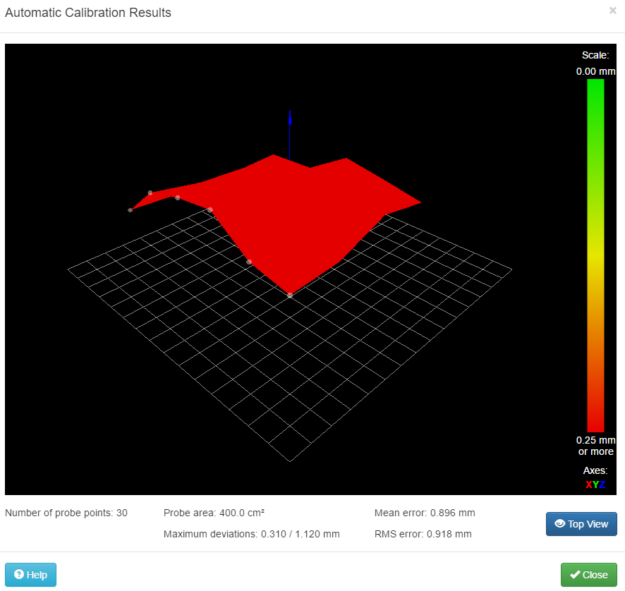
Then I performed the mesh bed compensation and read the results, again making very small adjustments to a single spring, then re-homing before running the mesh bed compensation again.
My results by doing this:

Any further adjustment and I would be chasing my tail as this is due to warpage.
-
PS. the up and down macros can be used to verify each corner is at equal trigger height after a mesh compensation and homing procedure…. the key here is really re-homing after each adjustment.
-
P.s i only use paper for the paper test not for probing or homing. you will need to mess with your z offest the more dialed in you get everything. basically i would jog the z up and down some times tighter and sometimes looser until i knew for sure there was equal pressure on all four corners each phase it would become that there was no pressure on all 4 corners and i had to adjust the z offset until i could feel the paper again on at least one corner then cycle through again
When i thought that pressure was equal on all four then i jogged up and down to check the trigger height of each corner to verify
-
As it sits right now, all 4 corners have the same trigger height with mesh bed disabled and all 4 corners feel the same pressure with paper test. With mesh bed enabled i see no difference regardless of where the head is on the bed
-
Also to get an idea of the amount of pressure needed (which is more than you would think) take a piece of paper and clamp calipers onto it until it reads 0.1 and move it in and out… the pressure is so tight that the paper almost wants to bunch up pushing it in
-
One more point i should bring up about bed surfaces, my printer came with an aluminum bed that is known for warping issues. I was able to offset this by putting a glass bed on top with a piece of black paper underneath.
Once i knew the bed was as close to level as i could get it (by reading the mesh map) I then used the mesh map to determin points around the glass that would benefit by either adding a paper clip or removing one and then rehoming then rerunning meshbed compensation with each removal or addition of paper clip to see how it affected everything. I finally found there were 3 ideal points to be clamped.
After that i fine tuned everything with the above mentioned methods.
-
Springs in my opinion are a joke, jack scews would be better. While springs can save the printhead from a bad crash the springs actually can make you chase your tail as just a little bump can make the bed out of level… which is one of the reasons when i thought everything was right i would purposly compress and let go of each spring until i knew the reading wasnt going to easily change on me.
Do yourself a favor, get rid of the springs and use jack screws instead if you can and print a carriage that can pop off if the bed ever crashes into the head.
I can provide an example of such a carriage if you are interested.
-
Also I do not know if it is necasssry but i made sure mesh bed compensation was disabled prior to rehoming and prior to each adjustment. Depending on how the compensation works not doing so could leave you scratching your head on why things are so off.
( you wont need to disable it to rehome once everything is level and you are happy with the mesh compensation results)