Inconsistent results with optical encoder wheel filament sensor
-
@JohnOCFII said in Inconsistent results with optical encoder wheel filament sensor:
Is there some way to configure M591 to, perhaps, not be so concerned with particulars, but to sense, for example, no movement for 5 seconds, and use that to trigger the sensor?
That seems like a reasonable feature request.
-
@arhi said in Inconsistent results with optical encoder wheel filament sensor:
I ended up configuring the sensor to use high span, minimum 20% and maximum 5000% and I reset the sensor on every layer (I added the script in slicer) and that solved my problems making it properly trigger if filament jams or snaps
Interesting. How long of a span did you use? Also - with such a large space and tolerance, I'm curious why it still would benefit from resetting on each layer. And finally -- How did you reset the data?
Thanks,
John
-
@JohnOCFII in layer change code in your slicer put something like
M98 P"filamentsensor.g"and create in sys filamentsensor.g where you configure your sensor.
in gcode.g where you would normally configure it use againM98 P"filamentsensor.g"instead configuring it there so you have only one place where you configure filament sensor...my filamentsensor.g:
M591 D0 P7 C"^e0stop" L0.124 R50:5000 E3 S1 A1 -
@JohnOCFII said in Inconsistent results with optical encoder wheel filament sensor:
with such a large space and tolerance, I'm curious why it still would benefit from resetting on each layer
'cause in slicer I can't set it to exec something every 100 layers, or every 10 minutes, but executing something every layer is simple and supported by every slicer so I'm reseting it every layer ... normally you would need to reset the readings once or twice during a normal print only but this works so I'm not touching it any more

(and yes, the 50:5000 can probbly be 80:200 when resseting every layer but as I said, works, not touching it any more
 )
) -
@arhi Excellent. Thanks for the detailed information. I'll get that a try!
-
@JohnOCFII yw, now, you have 2.6mm/pulse I have 0.124mm/pulse so there's huge difference in sensitivity between our sensors so you probably don't have the span as big as I do .. I think the reason I'm having these 5000% jumps are e.g. lot of retractions (PA related) and since I use rotary encore with too many pulses/rotation all those get registered while if you use less precision probably number of those will just be ignored
-
@arhi said in Inconsistent results with optical encoder wheel filament sensor:
@JohnOCFII yw, now, you have 2.6mm/pulse I have 0.124mm/pulse so there's huge difference in sensitivity between our sensors so you probably don't have the span as big as I do .. I think the reason I'm having these 5000% jumps are e.g. lot of retractions (PA related) and since I use rotary encore with too many pulses/rotation all those get registered while if you use less precision probably number of those will just be ignored
I've changed my distance per pulse quite a bit, as it jumps around. I've seen the measured amount be as low as 0.7 or as high as 2.6. When I thought it had settled out, I would change the L parameter. At one point I thought perhaps it was a faulty optical sensor, so I swapped that, but it remains inconsistent.
And yes, I do have a healthy retraction, as well as regular Z-hop and PA too.
John
-
I'm trying to eliminate variables to determine why I'm getting such inconsistent results, but I'm not making much progress.
- I modified my machine profile to have no retraction and no Z-hop
- I made sure Pressure Advance was disabled
- I created a simple vase-mode cylinder with no top and no bottom
The print ran at 15mm/sec.
After completion, these were my results:
Pulse-type filament monitor on pin (connlcd.encb,connlcd.3), disabled, sensitivity 1.200mm/pulse, allowed movement 50% to 1500%, check every 5.0mm, measured sensitivity 0.907mm/pulse, measured minimum 27%, maximum 2377% over 521.3mmThis is my M591 command:
M591 D0 P7 C"connlcd.encb" S0 R50:1500 L1.2 E5 A1Other than the prime line and a one layer, one loop skirt, this should have been, effectively, a simple 21 minute extrusion (plus simple vase-mode increase in Z for each layer). Does this imply I've got a physical issue? Some sticking or slipping in my sensor setup? It seems "smooth enough" when I pull filament through and watch the sensor wheel spin.
I'd love some additional ideas!
Thanks,
John
-
I've replaced the axle (A and B) and tried the same vase mode print again. Results very similar with this vase mode print. Next I need to try the "per layer" change suggested by @arhi
Pulse-type filament monitor on pin (connlcd.encb,connlcd.3), disabled, sensitivity 1.200mm/pulse, allowed movement 50% to 1500%, check every 5.0mm, measured sensitivity 1.030mm/pulse, measured minimum 28%, maximum 1649% over 524.1mm -
I'm following along, but not sure atm how to assist, so keep us posted.
-
@JohnOCFII said in Inconsistent results with optical encoder wheel filament sensor:
measured minimum 27%, maximum 2377% over 521.3mm
no retractions, no PA... IMHO this can mean only two things
- there is a problem with that encoder (it's sliping, or the light diode is not properly sensing the gaps, or a wire is loose, your output is floating and not properly going to Vcc/Vss, or ... dunno, something)
- there is a bug in the sensor code
I can't see the third option that can explain this.
What would be interesting to test is to attach a logic analyzer to the output of the sensor going to duet and logging the data
one question about [1], how is your electronics hooked up? schematic?
The way you configured itC"connlcd.encb"is no pullup/pulldown on the duet so duet expect you have a full swing 0 to 3v3 on this pin, do you have this or you maybe need a pullup or pulldown? You can easily configure pin to use pullup by adding ^ before the pin name soC"^connlcd.encb"dunno if duet support pull down I did not tryhttps://duet3d.dozuki.com/Wiki/RepRapFirmware_3_overview#Section_Pin_names
-
@arhi said in Inconsistent results with optical encoder wheel filament sensor:
What would be interesting to test is to attach a logic analyzer to the output of the sensor going to duet and logging the data
Hmm... I might have an old BitScope DSO around, but I'll have to see if I have a system I can run it from. Looks like they haven't updated software in a few years.
one question about [1], how is your electronics hooked up? schematic?
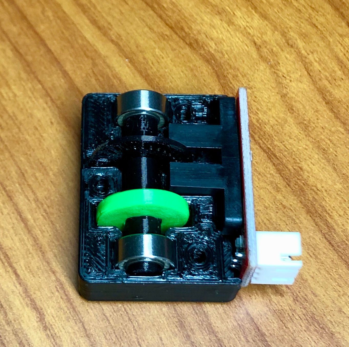
I hooked it up using the same connections I was using for my simple switched-based filament sensor. I'm using Pin1 in the CONNLCD 10-pin connector for 3.3V, Pin2 for GROUND, and Pin3 which is listed as STOP 10 (ENC_B).
https://duet3d.dozuki.com/Wiki/Duet_Wiring_Diagrams
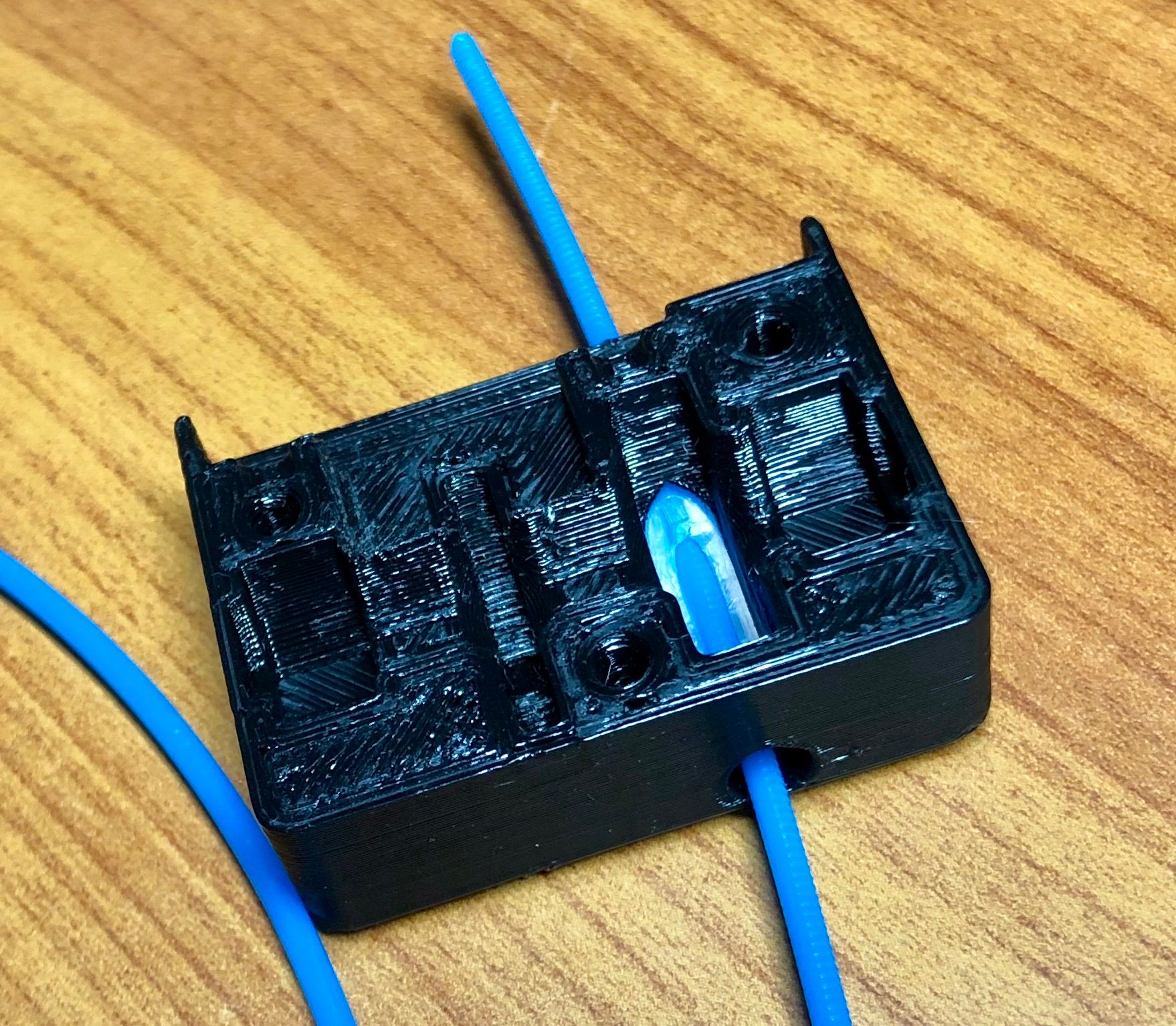
The sensor itself is a pretty basic optical endstop: https://www.ebay.com/itm/4-Pieces-Optical-Endstop-Limit-Switch-RAMPS-1-4-Board-3D-Printer-3Pin-Cable-A27/254260205504
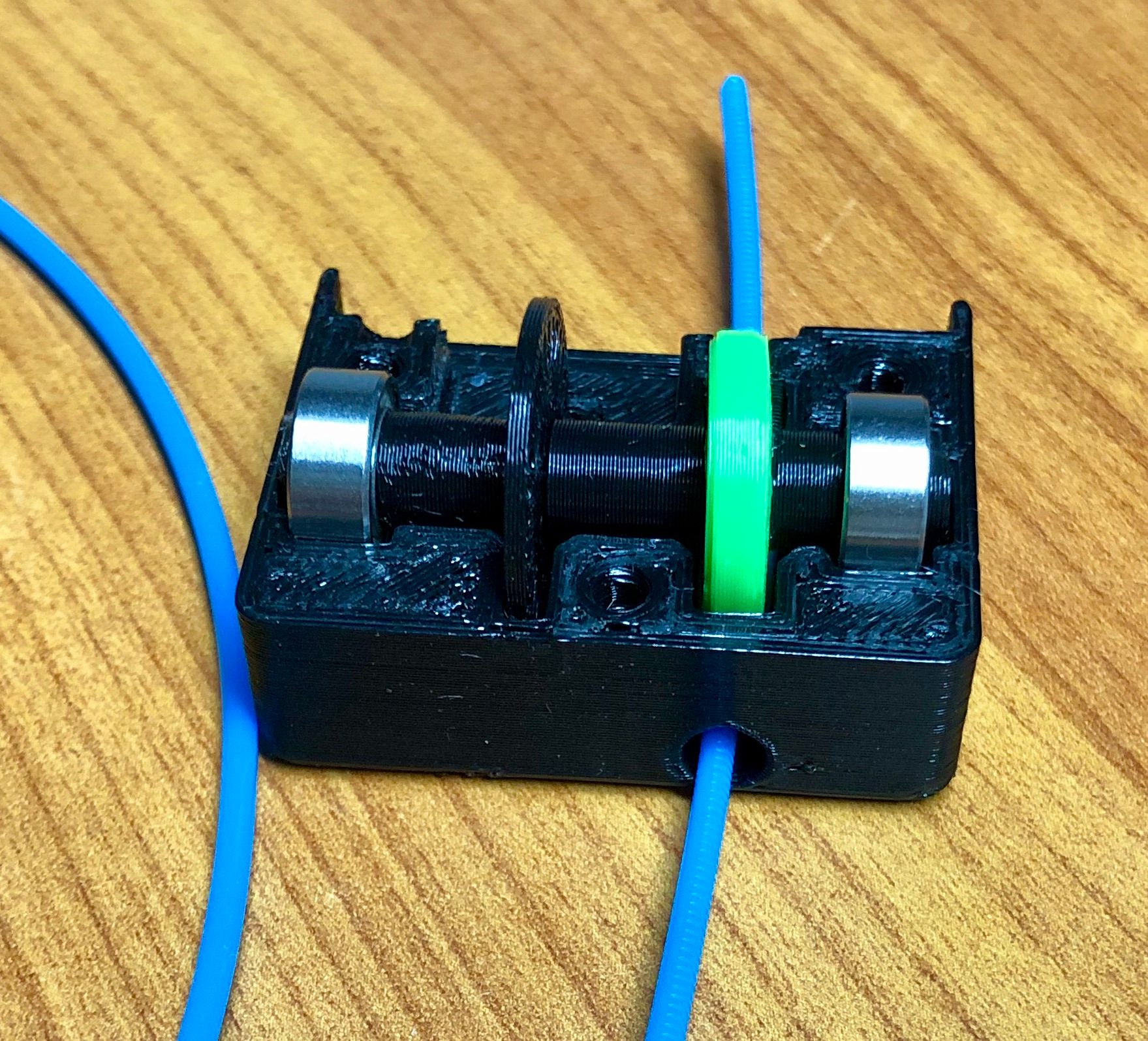
And again, the design is from @fractalengineer https://www.thingiverse.com/thing:4445504
The way you configured it
C"connlcd.encb"is no pullup/pulldown on the duet so duet expect you have a full swing 0 to 3v3 on this pin, do you have this or you maybe need a pullup or pulldown? You can easily configure pin to use pullup by adding ^ before the pin name soC"^connlcd.encb"dunno if duet support pull down I did not tryhttps://duet3d.dozuki.com/Wiki/RepRapFirmware_3_overview#Section_Pin_names
I'll try it with the pull-up.
I'll try these tomorrow. (US Central time here -- UTC-5 now for daylight saving time).
Thanks for the ideas!
-
the interrupter on those boards require pullup, wether pullup is already mounted on the pcb with the interrupter or not I don't know but testing with pullup on the duet is simple so nothing to lose by trying it IMHO

-
@arhi said in Inconsistent results with optical encoder wheel filament sensor:
the interrupter on those boards require pullup, wether pullup is already mounted on the pcb with the interrupter or not I don't know but testing with pullup on the duet is simple so nothing to lose by trying it IMHO

I added the pullup. Results seem more consistent. Still a broader range than I'd hope for a vase mode cylinder. I'll tweak the settings a bit - perhaps increase the measurement length, and try again.
Pulse-type filament monitor on pin (connlcd.encb,connlcd.3), disabled, sensitivity 1.200mm/pulse, allowed movement 50% to 1500%, check every 5.0mm, measured sensitivity 1.368mm/pulse, measured minimum 28%, maximum 428% over 521.3mm -
@JohnOCFII Sadly - continued testing shows similar wild results:
Pulse-type filament monitor on pin (connlcd.encb,connlcd.3), disabled, sensitivity 3.000mm/pulse, allowed movement 30% to 1500%, check every 10.0mm, measured sensitivity 1.731mm/pulse, measured minimum 72%, maximum 2606% over 1026.4mmI had changed the pulse sensitivity to be closer too what the measured results were on the previous tests, but now it moves again.
-
dunno that sound really bad, maybe move the connection to the
C"^e0stop"connector, dunno if it makes a difference but I'm not getting that big span on that pin -
If you can get that BitScope DSO to run I think that's a good way to move forward. Dunno if it's capable of "passtrough" grabbing like saleae, that would be ideal...
What is the interface material between the roller and the filament? And how is filament pressed to the roller? I was having a lot of slipping when my roller wheel was just a piece of PLA/ABS and since I didn't have any real flex to print it out of I made a roller wheel to have groove and added a small wide rubber band (I actually redesigned my sensor to fit that rubber band
 and that's the only small one I have, when it wares out I'll have to figure something new)
 -
@arhi said in Inconsistent results with optical encoder wheel filament sensor:
dunno that sound really bad, maybe move the connection to the
C"^e0stop"connector, dunno if it makes a difference but I'm not getting that big span on that pinThat'd be wild if a different connection made a difference. I'll have to think about that.
-
@arhi said in Inconsistent results with optical encoder wheel filament sensor:
If you can get that BitScope DSO to run I think that's a good way to move forward. Dunno if it's capable of "passtrough" grabbing like saleae, that would be ideal...
I did install the software and it appears to function. To be honest, I've never actually used it, so that may take some effort. :).
What is the interface material between the roller and the filament? And how is filament pressed to the roller?
It is a TPE roller pressing against the filament that is in a carved out channel of PTFE.


I've switched to a wheel with fewer, larger "spokes" as that was one recommendation from @fractalengineer
-
dunno how soft is that tpu, if you hold the encoder wheel witha hand and move the filament, how much force you need to apply to move it (as it will be slipping 'cause you are holding the encoder wheel) ?
a possible issue I see here is that many black plastic filaments are actually transparent to IR light and does not work reliably, or at all, as a light stop for the gap sensors. back in the day of darwin I had to tape the alu foil over the printed blade (and then painting it black with marker) going into the sensor for sensor to register it every time and at the same location. I haven't used printed wheels for more than a decade as when I make pcb's at home when I do films I have to pay for full width of the film (30 or 60cm) so I add to the film different encoder wheel designs I can later use in designes like this (high precision, low precision...).
I believe you can do the same here, just tape the piece of alu foil over the wheel and cut the holes trough alu matching holes on the plastic using a blade, black marker paint the alu foil after that and the transparency of the plastic issue should be gone