Robotic kinematics
-
@tony73 I tried the hinge with the rotating plate now, it is very stiff:
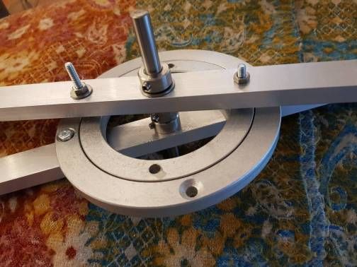
The play can be finetuned with the screws. I can put the elements even closer together when I get countersunk screws.
Edit: I was receiving other plates now, they have very different quality. The 300 mm diameter one is not round and I will have to rework him. Some have too much play. Some are good. And some don't have the boring holes at the correct position (opposite through the center)...
-
@tony73 I received 225 mm diameter rotation plates now, the resulting robot will look crazy. Maybe it's better to use worm gears. Which ratio do you get with your planned construction?
-
Hi! even if sometimes I don't write, I keep watching your updates! I studied a bit on the various types of worm gearboxes that you made me discover!
the best solution would be this, globoid worm, I tried to understand and designed this
 I would like to finish it and print it in abs to understand if the calculations come back, the measurements are mm I would have a smaller footprint! this has pitch 50 teeth about 2.83 (it was a test I didn't care about the pitch) so of reduction of 1/50 I could build it on the lathe, but I have to prepare some things to create the globoid screw (the reduction can be done in various ways 1/20, 1/45, 1/80, 1/100) are examples, you just have to decide the right ratio what can be better, you can make any ratio always small footprint of the reducer! but I don't know which ratio can be the best to use, I will need several different ones for the 5 axes!
this globoid screw would have contact with at least 6 gear teeth, as opposed to the normal straight screw which only makes good contact on one gear tooth!
-
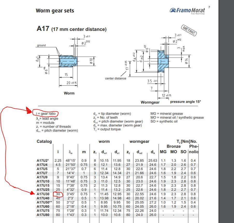
@tony73 a stepper can achieve 1000 rotations/min, which is about 16 rotations per second. But for good torque, in most cases a maximum of about 5 rotations/s are used. This are 5*360=1800 degrees. With a 1:30 ratio, this is 60 degrees per second. The speed depends on the arm length, a 20 cm arm 2 and 3 length which you used means 60 degree for 20 cm rotating, arm2+3 maybe 30 to 35 cm, so 300...350 mm/s. This will probably be more than you can use for the extrusion of the filament. I would recommend using 1:30.
A different aspect is the maximum payload of the gear. Maybe you can research typical maximum payloads for a worm gear. The most critical payload will be for axis 2, because it adds arms 2 until the end, the hotend.
I made me a spreadsheet to calculate the loads (LibreOffice Calc file):
=> please contact me here or with chat if you need the file. It changes rapidly, I don't want to upload it every time it changes.
In the third register is the interesting calculation:
- left g means weight left side of an axis in g
- dist l cm means distance from the axis
- torque Ncm is the torque and depends on distance and weight
- detent torque is when the current is off and should be near 0 for a belt based gear
- CW means counterweight
What can be seen is that the weights of Axis 5 and 4 are critical, because they add to axis 3's and 2's loads, so minimizing is a goal. The weights roughly double with each axis from 5 to 1.
-
@JoergS5
if I understand correctly I should do the 1/30 gear reducer and this would be the calculation for M92 (200 * 30 * 16/360 = 266.6666666667) and could it be suitable for all 5 actuators? -
@tony73 in general yes and the calculation is correct.
But maybe you don't need 1:30 for Axis 5, because the gear will add some weight there. And Axis 4 is always vertical, a lower gear may be sufficient. But if you want to standardize and use the same gear everywhere, you can do it this way. At Axis 1 and 5 I would use only a gear without backlash, because you'll have many direction changes without force up/down.
I would create one worm drive and measure weight, backlash, maximum load and stability/no vibration to all directions, before deciding whether to use it at all axes.
I will try to make Axis 4 and 5 as light as possible, but want to avoid Bowden*). Because I want to create a toolchanger, which is easier to implement with a direct drive extruder.
*) Bowden as counterweight at Axis 3 would be a nice solution with very low weight at axis 5, but I will not use it.
-
This post is deleted! -
@tony73 I am sorry, I don't understand your sentences.
You mean I use wrong material?
What do you mean I protest against using aluminium? I didn't make a statement of material of the worm gear. -
This post is deleted! -
Hi! Sorry for my English ! I said that badly !
your quote: I would create one worm drive and measure weight, backlash, maximum load and stability/no vibration to all directions, before deciding whether to use it at all axes.
idea how to try a screw gear motor!
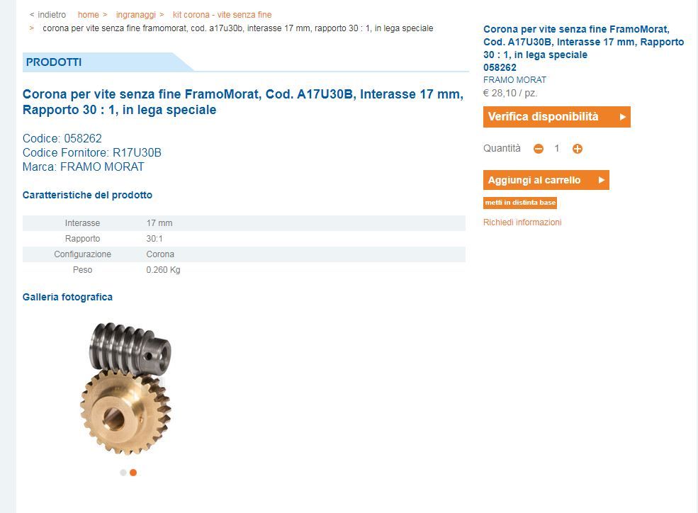
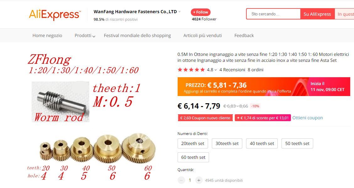
the weight is a bit excessive! 260 grams, but it can be an idea to try the gear motor, for the gear motor structure I would use this!
I will do globoid worm gear and cog with lathe, and would like to use aluminum profile for box as proof!
-
@tony73 sounds like a good plan. You made a plan of the worm drive, but without the connection to the arms. If you like, make a plan including this connection and we can discuss.
The output torque T2 in Nm is between 1.8 and 2.8 Nm (depending on lubrication MG/MO/SO), which means:
180 to 280 g with a 1 m arm,
450 to 700 g with 40 cm (arm 2 and 3 in your config),
900 to 1400 g with a 20 cm arm.You will probably need a counterweight at Axis 2, Axis 3 could work without (depends on how many weight you have for Extruder, Hotend, Steppers Axis 4 and 5).
-
do you want to try to make a worm gear reducer to test the robot, or am I wrong to understand?
-
This post is deleted! -
@JoergS5
ok! I understood ! I'll let you know as soon as I have something built! -
This post is deleted! -
This post is deleted! -
@tony73 I want to sort the ideas I had and delete the unsorted blogs:
- please don't feel obligated to build a worm drive now to help with building the prototype. The worm drive may not work, but getting experience with it is worthful of course.
- from my gear tests, I think it is best to use as big last wheel as possible, because of the forces involved and precision sideways, leading the arm into the intended direction and stability into the intended direction.
- counterweights should be avoided or they should be near the axis, for better acceleration and low wobbling, an exception will be axis 2, which has the burden of arms 2 to 5 and extruder and the biggest leverage
I've calculated all for a solution with belt based gears and found solutions where they are in balance when powered off. I build it now.
There are two robots which impress me and I'll try some of their ideas: Kuka KR 700 and bytronic 5ARA (UK company, R12 from ST Robotics similar).
-
@tony73 said in Robotic kinematics:
to use aluminum profile for box as proof
this is a good idea: using aluminium profiles for a part of the prototype. I have already many parts with wrong holes in it, the profiles will spare some money for testing where the holes shall be. I am currently using aluminium profiles to construct Axis 1.
I rebuilt axis 2, 3 and 4 yesterday, proceeding with axis 1, then finish the hotend.
-
@JoergS5
Hi! i looked at robot arm R12 and it looks great for using pulleys and belts! which one are you building the kuka kr 700 or R12? -
@tony73 I am trying the counterweight idea of R12. I install two steppers left of axis 3 for axis 3 and axis 4, and one big Nema 23 left of Axis 2 for axis 2. With the help of aluminium profiles it was very easy to install axis 1. Arm 2 length is 270 mm, arm 3 is 230 mm, arm 4 is 180 mm and arm 5 is 100 mm.
The Kuka KR 700 is similar to what I built to run in R1 mode without a stepper for Axis 4. This is useful for users who want to use 4 steppers for the axes and 1 stepper for the extruder, so in total 5, because the Duet boards often have 5 drivers (and according to the article which I mentioned somewhere above the precision is better).