Duet 2 Wifi shutdown immediately after restart
-
Hi all,
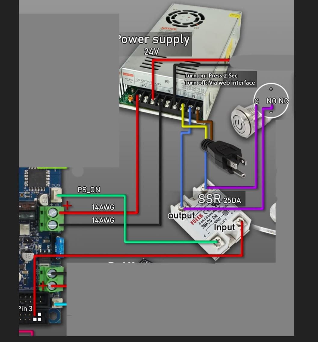
i just end to build my printer, i'm using a regular 24v 500w psu, a ssr 25DA and a temporary 220v switch to allow auto shutdown.
M81 is working fine, i put M80 at the start of config.g.
Every time i chose to restart the board when config.g is saved, the board restarts but immediately the psu turns off.
The PSU is set to 24.2v.
Any suggestion?
Thanks -
Can you show us your config.g and maybe a diagram of how you have things wired?
-
This is my config
; Configuration file for Duet WiFi (firmware version 3) ; executed by the firmware on start-up ; ; generated by RepRapFirmware Configuration Tool v3.1.4 on Tue Aug 11 2020 17:42:02 GMT-0500 (Central Daylight Time) ; General preferences M80 ; Turns on the ATX power supply G90 ; send absolute coordinates... M83 ; ...but relative extruder moves M550 P"BLV Cube" ; set printer name M669 K1 ; Select CoreXY mode ; Network M552 S1 ; enable network M586 P0 S1 ; enable HTTP M586 P1 S0 ; disable FTP M586 P2 S0 ; disable Telnet ; Drives M569 P0 S1 ; physical drive 0 goes forwards M569 P1 S0 ; physical drive 1 goes backwards M569 P2 S0 ; physical drive 2 goes backwards M569 P3 S0 ; physical drive 3 goes backwards M569 P4 S0 ; physical drive 3 goes backwards M671 X-64.75:366.75 Y150:150 S10 ; leadscrew pivot point: Left -65:150, Right 364:150 ;Distance between leadscrews = 429.5mm ;Center of leadscrew 12.5mm away from outside edge of 2020 bed carriage extrusion ;If everything is centered correctly the center of the leadscrew is 150mm away from front and back of the bed M584 X0 Y1 Z2:4 E3 ; set drive mapping Z2=Left, Z4=Right M350 X32 Y32 Z16 E16 I1 ; configure microstepping with interpolation M92 X200.00 Y200.00 Z400.00 E406.56 ; set steps per mm M566 X700.00 Y700.00 Z240.00 E2000.00 ; set maximum instantaneous speed changes (mm/min) M203 X18000.00 Y18000.00 Z1000.00 E2000.00 ; set maximum speeds (mm/min) M201 X3000.00 Y3000.00 Z100.00 E4000.00 ; set accelerations (mm/s^2) M906 X1600 Y1600 Z800 E1600 I30 ; set motor currents (mA) and motor idle factor in per cent M84 S120 ; Set idle timeout ; Axis Limits M208 X-23 Y0 Z0 S1 ; set axis min M208 X320 Y321 Z350 S0 ; set axis max ; Endstops M574 X1 S1 P"xstop" ; configure active-high endstop for low end on X via pin xstop M574 Y2 S1 P"ystop" ; configure active-high endstop for high end on Y via pin ystop M574 Z1 S2 ; configure Z-probe endstop for low end on Z M591 D0 P1 C"e0stop" S1 ; configure filament runout sensor for high end on extruder drive 0 via pin i03.in ; Z-Probe M950 S0 C"exp.heater3" ; create servo pin 0 for BLTouch M558 P9 C"^zprobe.in" H5 F300 T9000 ; set Z probe type to bltouch and the dive height + speeds G31 P500 X0 Y0 Z.780 ; set Z probe trigger value, offset and trigger height M557 X30:270 Y30:270 P4 ; define mesh grid ; Heaters M308 S0 P"bedtemp" Y"thermistor" A"Bed" T100000 B4725 C0.0000000706 R4700 ; configure sensor 0 as thermistor on pin bedtemp M950 H0 C"bedheat" T0 ; create bed heater output on bedheat and map it to sensor 0 M307 H0 A284.0 C843.8 D11.0 B0 ; Heatbed PID M140 H0 ; map heated bed to heater 0 M143 H0 S120 ; set temperature limit for heater 0 to 120C M308 S1 P"e0temp" Y"thermistor" A"Hotend" T100000 B4725 C0.0000000706 R4700 ; configure sensor 1 as thermistor on pin e0temp M950 H1 C"e0heat" T1 ; create nozzle heater output on e0heat and map it to sensor 1 M307 H1 A284.1 C115.5 D2.6 V23.9 S0.9 B0 ; Hotend PID .4mm M143 H1 S260 ; set temperature limit for heater 0 to 260C M308 S2 P"mcu-temp" Y"mcu-temp" A"Duet Board" ; Configure MCU sensor ; Fans M950 F0 C"fan0" Q500 ; create fan 0 on pin fan0 and set its frequency M106 P0 C"MB Fan" T35:55 H2 ; set fan 0 value. Thermostatic control is turned on M950 F1 C"fan1" Q500 ; create fan 1 on pin fan1 and set its frequency M106 P1 C"Layer fan" S0 H-1 ; set fan 1 value. Thermostatic control is turned off M950 F2 C"fan2" Q500 ; create fan 2 on pin fan2 and set its frequency M106 P2 C"HE Fan" S1 H1 T40 ; set fan 2 value. Thermostatic control is turned off ; Tools M563 P0 D0 H1 F1 ; define tool 0 G10 P0 X0 Y0 Z0 ; set tool 0 axis offsets G10 P0 R0 S0 ; set initial tool 0 active and standby temperatures to 0C ; Custom settings M564 H0 ; Let the Jog buttons work blv: added to allow jog buttons ; Miscellaneous M575 P1 S1 B57600 ; enable support for PanelDue I follow exaclty this wiring,
-
Please help me
-
Resetting the board has the same effect as M81 on the PS_ON pin, so that is expected behaviour even if not desired.
You can move the PS_ON pin to GND while setting up the printer to work around it, and move it back to PS_ON when you need to turn the printer off from web.
-
You could try putting capacitor on SSR input.