Robotic kinematics
-
I think making cycloidal reducers yourself is preferable to harmonic drives. The flexspline is hard to make without metal and more often than not you end up with a reducer with very low durability and torsional rigidity. Cycloidals on the other hand use just rigid components and are a lot easier to make with printing. And offer a lot more torsional strength.
-
@roiki11Did you make some yourself, this would be interesting. What I know is that the gear ratio is limited in the range of 1:8 in the most examples I saw. So they are often combined with an added 1:3 belt gear between stepper and cycloid gear.
-
@JoergS5
Yes I've made some. Somewhat big with 72.5 reduction.The reduction ratio is not limited at all since you can use multiple stages. You can also get 30:1 reduction quite easily on a single stage too. Though if small size is a priority then that can limit the cycloidal ratio.
-
@roiki11 are they open source and you can share it please if possible. If not, maybe you can provide a hint where to start or whether you started development from an example. And did you make them 3D printed or with metal?
There are some thingiverse and youtube builds, but one never knows which ones are good quality and which not, unfortunately.
The robot hinges are better with bigger diameter imho, because they give added sideways stability. I think 10 cm diameter is ok for a printer for print area 40 or 50 cm each dimenstion.
-
@JoergS5 said in Robotic kinematics:
@roiki11 are they open source and you can share it. If not, maybe you can provide a hint where to start.
There are some thingiverse and youtube builds, but one never knows which ones are good quality and which not, unfortunately.The robot hinges are better with bigger diameter imho, because they give added sideways stability. I think 10 cm diameter is ok for a printer for print area 40 or 50 cm each dimenstion.
The one I'm working now is about 140mm in diameter. It's not completely finished yet since I have some parts to print and final fit. It's completely working though. I can link the fusion file sometime.
You can also check opencyre. it's a pretty good design. There's also a
Script for fusion for generating the cycloidal gears. I used that which made the design work really easy. https://github.com/mawildoer/cycloidal_generatorJust remember that the reduction ratio is "<number of pins> - 1" or the number of lobes on the rotor.
-
@roiki11 thank you for the links, I will give cycloidal a try. I agree with you that the cycloidal drive is easier to build.
Do you plan to build a robot with it also?
-
@JoergS5
good morning! were you able to try the print? -
@tony73 no, I could not finish 5th axis. It won't take much longer, but I don't want to hurry. I changed my design to a 20/60 * 20/60 * 20/60 belt gear, resulting in 1:27. The result is a 150 g lighter axis 5.
The tension of the long belts is a real problem, resulting in flexing and imprecision. When finished prototype 1, I'll start immediately with the construction of a cycloidal gear, first for axis 2. The calculations of weights and torque are valuable, because implementing cycloidal gear with low torque when rotating will be good for precision probably.
-
@JoergS5 said in Robotic kinematics:
@roiki11 thank you for the links, I will give cycloidal a try. I agree with you that the cycloidal drive is easier to build.
Do you plan to build a robot with it also?
Yes I'm building a 6 axis robot arm. Mostly for camera work and shits and giggles.
It's a bit on hold now though with covid and all.
-
@roiki11 you're invited to comment or distribute ideas on the robot constructions if you like.
-
@tony73 do you want to try cycloidal also, or proceed with harmonic drive? Both is possible and valuable (cycloidal to try to optimize, harmonic to compare both). I'll try cycloidal next, although I have the original harmonic drives as patterns. But creation of the flexspline seems difficult to me.
-
@JoergS5
Hi! can you tell me a commercial arm robot that uses cycloidal gearboxes? can they have zero play like harmonic drives? I see more complicated to build cycloidal gearboxes in (steel) and there is always the problem of the junction point between the gearbox and the two arms of the robot, the most logical solution is a crossed roller bearing and I think also the lightest one, another is to use two tapered roller bearings, the cost is very much lower, but the support must be built to contain them with a lathe or a cnc, but the weight is certainly higher! Do your harmonic drives come complete with crossed roller bearings? if yes, you have a huge advantage, that type of bearing, for what I understand as it is! allows you to merge two robot links! I believe that the robot you are building, with belts and pulleys (type R12), is an excellent solution to be able to give many people the possibility of making a robot arm! -
@tony73 I will certainly finish prototype 1 (or should I call it Model 1) with belt gears, because someone can build it without special tools. Only some boring and a saw (even a hacksaw is sufficient).
My commercial harmonic drives have ball bearings for the wave generator, not cross roller bearings.
Cycloidal is said to be zero backlash also, but I have no experience which one is easier to build. It is only that flexspline will be complicated. But with a high gear ratio (many teeth), cycloidal needs to be precisely created also, same like harmonic drive. So I am not sure.
If I am unsure of something, I generally end up buying/making both....
I think the commercial robots use harmonic drive mainly. The noncommercial ones often cycloidal (like Sixi 2).
I wanted to avoid using the harmonic drives which I bought used, because the robot then cannot be copied. 5 Axes with 200 $ minimum means 1000 $ for gears alone. Maybe I use it for Axis 5, I have a combination of Faulhaber stepper with Harmonic drive, which is beautifully small.
What I can certainly make, is compare the commercial harmonic drive with a DIY harmonic drive, cycloidal or belt based gear.
PS I'm sorry that the prototype takes so long (our first discussion was in September, so 3 months now). I underestimated the effort and I had to learn a lot. I feel more like a marathon runner than a sprinter!
-
@JoergS5
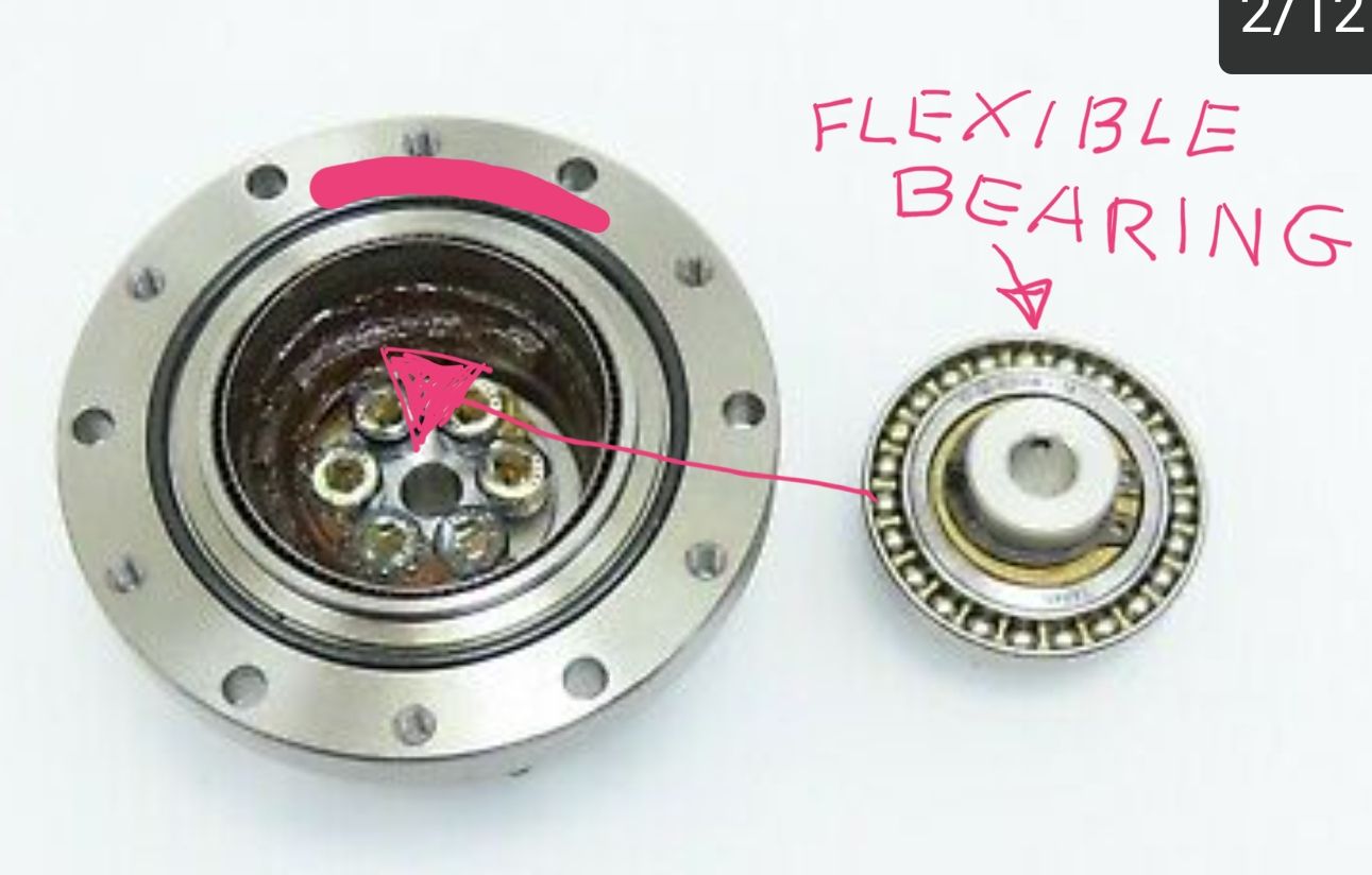
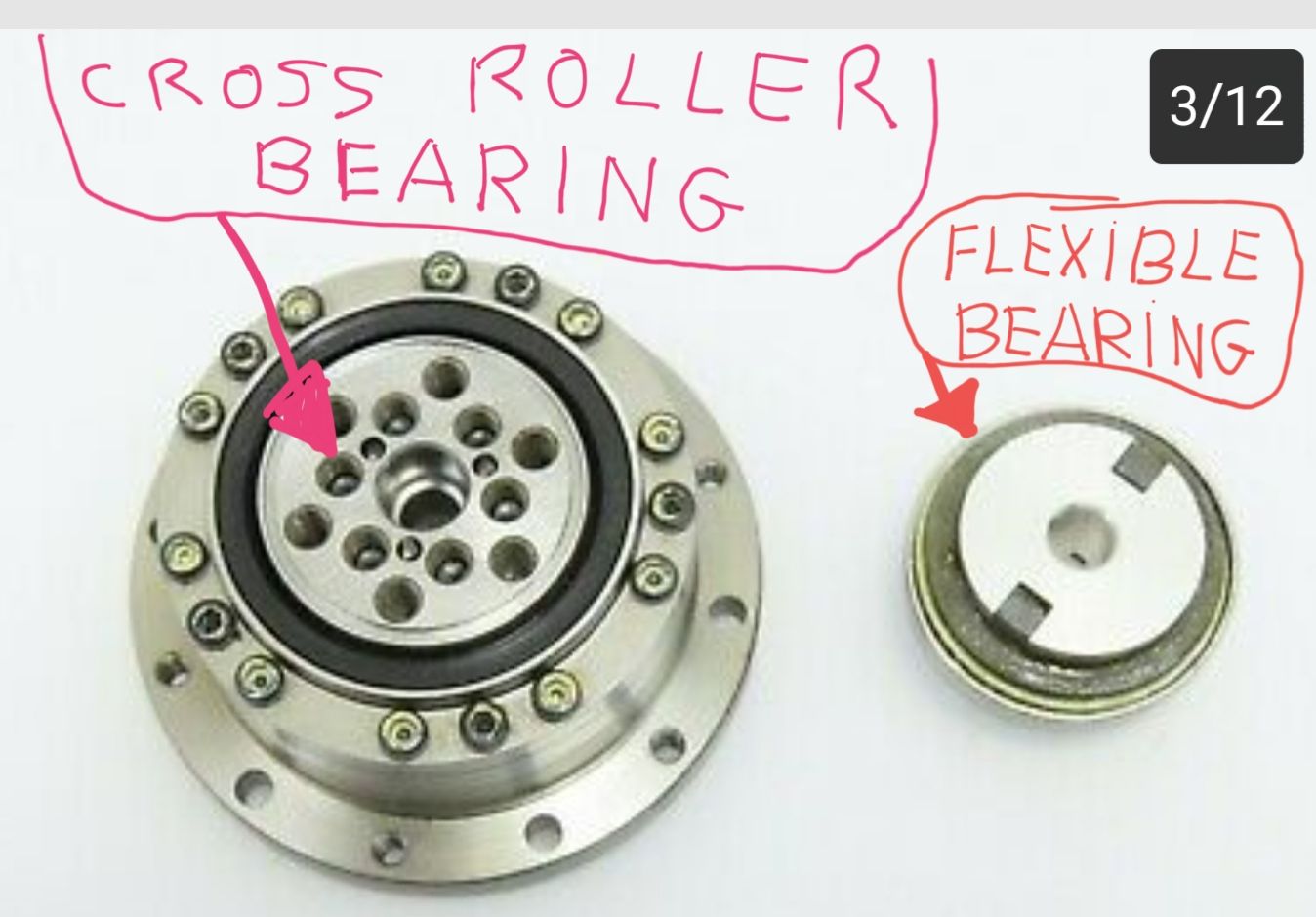
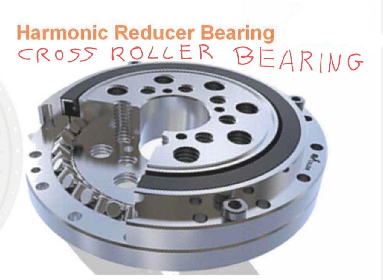
the time it takes is not a problem! I figured it wouldn't be a short job! you're already doing a lot! the bearing you say is ball bearing and the one that creates the deformation waves on the teeth of the harmonic bell, what I say (crossed rollers) goes to the opposite side of the harmonic bell, to create (the articulation and the junction) between harmonic drive and two links of a robot!


I'm buying a harmonic drive complete with used crossed roller bearing! I want to see how it's done, to try to reproduce it! I'm curious to try! but it's not a good idea to make them at home! it will take many hours of work, much better to buy them used, hoping that they are always good! but I will follow your R12 type idea with belts and pulleys. ( harmonic drives printed in 3d with abs or rubber-like material for the bell, I have already tried, nice to see to study the operation! but high precision is missing! ) I have seen that even 1 hundredth of a millimeter on this type of gearbox can be a problem!
-
@tony73 thank you for explaining, then I have a harmonic drive with cross roller bearing also!! Because I have bought two used like your image with cross roller bearing.
=> Do you know whether the height of the rollers is less than the diameter? I think this should be the case for the roller bearing have a bit of play to roll. I bought enough 5 mm high, 5 mm diameter rollers for a DIY cross roller bearing, but I doubt it is correct.
The problem with belt gears are long distances (30 cm) for axis 4, they need to be tensioned good. I have multiple belt tensioners already, with some success. The belt gears themself are working good, and producing is not so complicated. However I needed to buy closed belts mutliple times, because of changing distances.
-
@tony73 said in Robotic kinematics:
harmonic drives printed in 3d with abs or rubber-like material for the bell, I have already tried
When building the parallel scara printer, I needed two big wheels with teeth. I made it from wood, and produced the teeth by using closed belt over the wheel and bringing epoxy between wheel and belt. This works good, because the belt - epoxy connection is not firm, after drying epoxy the belt can be removed easily and reused. I did dry the epoxy an hour before using it, because it flows away easily. It depends on the epoxy how long to wait. *)
I thought about the same process to create the outer, circular spline. Using 240 teeth belt for the outer ring with epoxy (belt turned, teeth outside) and 232 teeth for the flexspline would give 1: 232/(240-232) = 1:29. The distance between outer and flexsplice is about 1.27 mm. (I am not sure about the 1.27 mm, because at which height on the belt is to be measured? The teeth of GT2 have about 0.7 mm height). It could work. Another possibility is eg. outer 360 teeth, flexspline 350 teeth: 1: 350/(360-350) = 1:35, distance 1.59 mm.
*) BTW I though about using a closed belt directly on the wheel, running belt-on-belt. But this doesn't work: the wheel bends the belt so much that the teeth do not fit after a short distance like 1-2 cm, even for wheels with 30 cm diameter.
-
@JoergS5
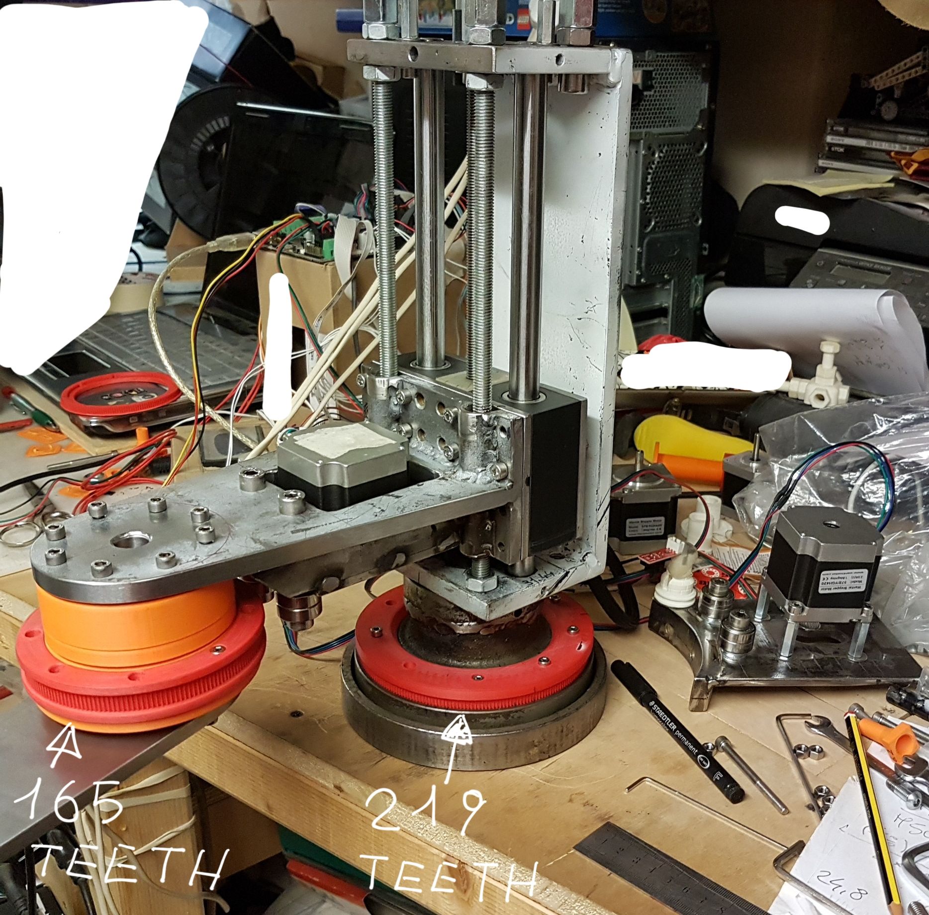
I believe that the cylinders for the cross roller bearing have the same length and diameter! in order to be crossed in the slide channel! I found two Chinese sites one sells crossed roller bearings of various sizes, ľother flexible bearing for the harmonic bell, the costs of the crossed roller bearings are about 130 euros, that of flexible bearings for the harmonic bell about 30 euros! i think it is better to buy them. you had a great idea! to use a resin to recreate the teeth of a pulley! the other alternative is to print them, for my scara I had to do about 4 or 5 tests to find the right tolerance of the teeth of the 2 pulleys, X 219 teeth Y 165 teeth
the first periods! total chaos!
-
@tony73 they are looking good.
I think it would be fun to DIY cross roller bearings, I'll try it, 3D print parts of it first and postprocess with router. Axis 1 is ideal for it, because a big diameter is good for z precision and all wires can be routed through the middle.
-
@JoergS5
can you tell me where you bought the cylinders for the cross roller bearing? -
You can make cross roller bearings with a 3d printer. I've made a few with steel rollers and they came out nicely. Of course they're not going to compare to metal ones so their usage is a bit questionable. Might be just easier to print mounts for normal ball bearings since you're not going to overload them anyway.
https://www.instructables.com/Create-a-Parametric-3d-printable-Slew-Bearing-With/