Robotic kinematics
-
@JoergS5
the time it takes is not a problem! I figured it wouldn't be a short job! you're already doing a lot! the bearing you say is ball bearing and the one that creates the deformation waves on the teeth of the harmonic bell, what I say (crossed rollers) goes to the opposite side of the harmonic bell, to create (the articulation and the junction) between harmonic drive and two links of a robot!
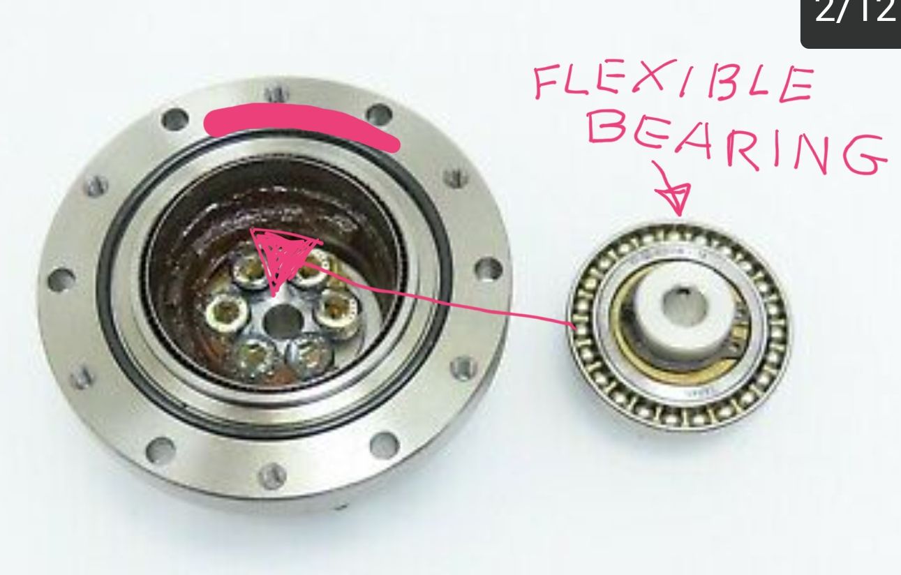
I'm buying a harmonic drive complete with used crossed roller bearing! I want to see how it's done, to try to reproduce it! I'm curious to try! but it's not a good idea to make them at home! it will take many hours of work, much better to buy them used, hoping that they are always good! but I will follow your R12 type idea with belts and pulleys. ( harmonic drives printed in 3d with abs or rubber-like material for the bell, I have already tried, nice to see to study the operation! but high precision is missing! ) I have seen that even 1 hundredth of a millimeter on this type of gearbox can be a problem!
-
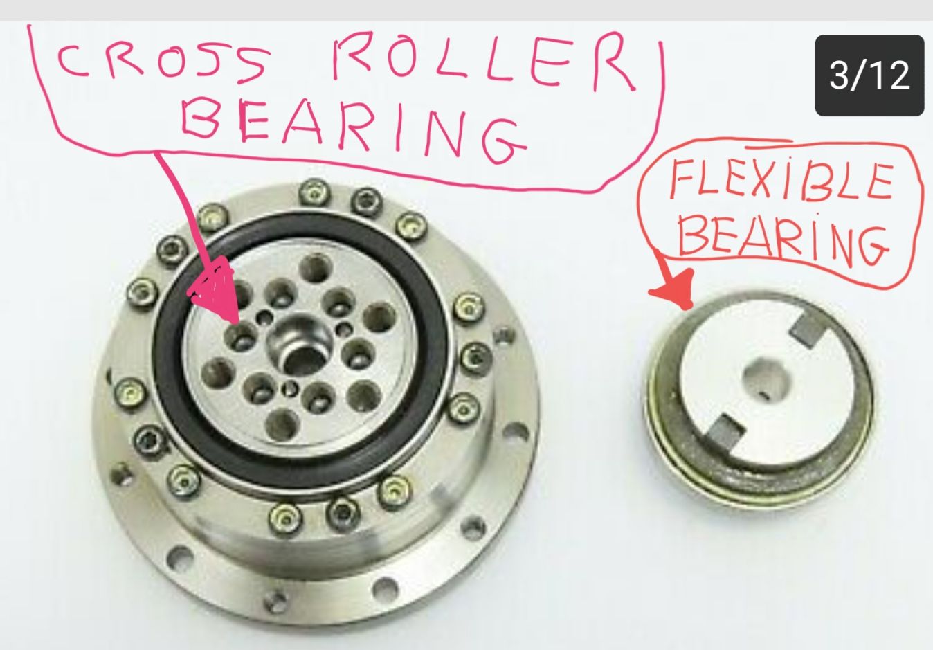
@tony73 thank you for explaining, then I have a harmonic drive with cross roller bearing also!! Because I have bought two used like your image with cross roller bearing.
=> Do you know whether the height of the rollers is less than the diameter? I think this should be the case for the roller bearing have a bit of play to roll. I bought enough 5 mm high, 5 mm diameter rollers for a DIY cross roller bearing, but I doubt it is correct.
The problem with belt gears are long distances (30 cm) for axis 4, they need to be tensioned good. I have multiple belt tensioners already, with some success. The belt gears themself are working good, and producing is not so complicated. However I needed to buy closed belts mutliple times, because of changing distances.
-
@tony73 said in Robotic kinematics:
harmonic drives printed in 3d with abs or rubber-like material for the bell, I have already tried
When building the parallel scara printer, I needed two big wheels with teeth. I made it from wood, and produced the teeth by using closed belt over the wheel and bringing epoxy between wheel and belt. This works good, because the belt - epoxy connection is not firm, after drying epoxy the belt can be removed easily and reused. I did dry the epoxy an hour before using it, because it flows away easily. It depends on the epoxy how long to wait. *)
I thought about the same process to create the outer, circular spline. Using 240 teeth belt for the outer ring with epoxy (belt turned, teeth outside) and 232 teeth for the flexspline would give 1: 232/(240-232) = 1:29. The distance between outer and flexsplice is about 1.27 mm. (I am not sure about the 1.27 mm, because at which height on the belt is to be measured? The teeth of GT2 have about 0.7 mm height). It could work. Another possibility is eg. outer 360 teeth, flexspline 350 teeth: 1: 350/(360-350) = 1:35, distance 1.59 mm.
*) BTW I though about using a closed belt directly on the wheel, running belt-on-belt. But this doesn't work: the wheel bends the belt so much that the teeth do not fit after a short distance like 1-2 cm, even for wheels with 30 cm diameter.
-
@JoergS5
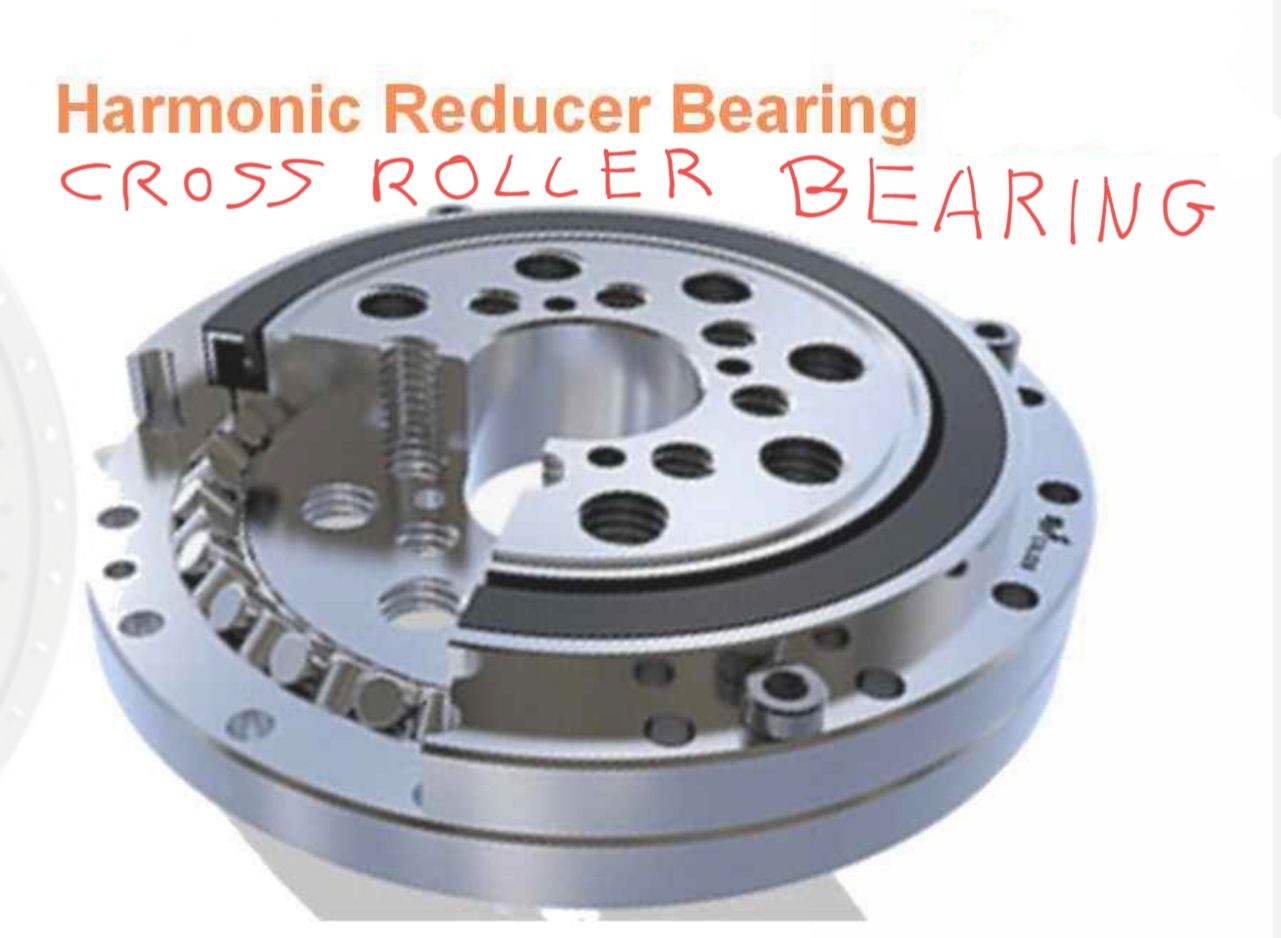
I believe that the cylinders for the cross roller bearing have the same length and diameter! in order to be crossed in the slide channel! I found two Chinese sites one sells crossed roller bearings of various sizes, ľother flexible bearing for the harmonic bell, the costs of the crossed roller bearings are about 130 euros, that of flexible bearings for the harmonic bell about 30 euros! i think it is better to buy them. you had a great idea! to use a resin to recreate the teeth of a pulley! the other alternative is to print them, for my scara I had to do about 4 or 5 tests to find the right tolerance of the teeth of the 2 pulleys, X 219 teeth Y 165 teeth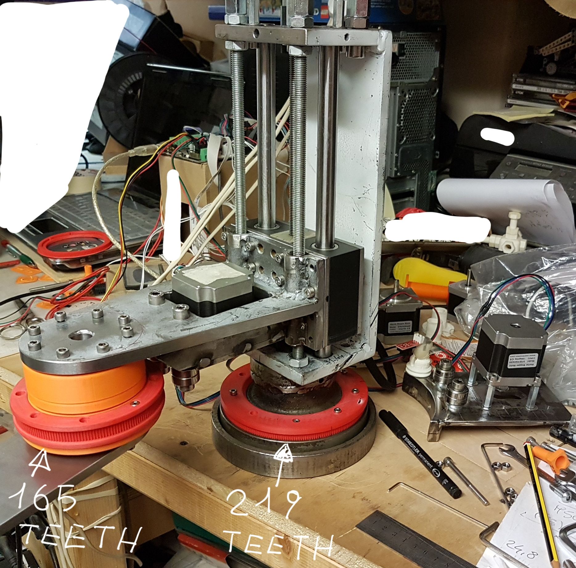
the first periods! total chaos!
-
@tony73 they are looking good.
I think it would be fun to DIY cross roller bearings, I'll try it, 3D print parts of it first and postprocess with router. Axis 1 is ideal for it, because a big diameter is good for z precision and all wires can be routed through the middle.
-
@JoergS5
can you tell me where you bought the cylinders for the cross roller bearing? -
You can make cross roller bearings with a 3d printer. I've made a few with steel rollers and they came out nicely. Of course they're not going to compare to metal ones so their usage is a bit questionable. Might be just easier to print mounts for normal ball bearings since you're not going to overload them anyway.
https://www.instructables.com/Create-a-Parametric-3d-printable-Slew-Bearing-With/
-
@roiki11 I saw them in the past and I was impressed! Are the orange rollers eatable
") ?
?Some of my buys and makings are just from fascination about the technology. Trying to make a cross roller bearing in metal is in this category. You're right, normal ball bearings are easier, and I use the ones I showed above. They have 250 and 300 mm diameter. The 300 mm was crap, I have to use the 250 mm version.
-
@tony73 said in Robotic kinematics:
where you bought the cylinders
I buy balls and rollers at Kugel-Winnie in germany. He has a good selection of different tolerance classes, often G10 or better. If you buy, you should buy in one shot what you need, because the tolerance classes are in respect to this sample.
His delivery time is a few days, not the fastest, but I'm very satisfied with the quality. -
Only if you like indigestion.
I've made mine with steel rollers from eBay. They worked fine and were better than plastic. Search for dowel pins and you should find them. 100 cost me about 15-30, depending on size.
-
@roiki11 do you know whether diameter of the rollers are the same as the height, or do I need different sizes? I thought about it: the rollers roll at the side, but grind at the fronts, so diameter should be a bit bigger than the height.
-
The rollers are symmetrical.
-
@roiki11 ok, thank you!
-
I've started to describe my first prototype now, which I call "Type 1" here: https://forum.duet3d.com/topic/20209/robot-type-1-45-cm-belt-gear-direct-drive-r0
The main discussion about gear types, firmware, future direction, status etc. will stay here. -
@JoergS5
Hi! were you able to try the print? -
@tony73 I have some tasks left, but I see the finish line!
The taks left:
- belt tension of big rotation plates is not good enough
- endstops
- calibration of Axis 1 by 3 points
- Axis 1 replace aluminium extrusion through hollow square
- hotend assembly
- better precision of hinges by replacing 8 mm holes by 16 mm F688 ball bearings (currently one arm with 16 mm, one with 8 mm each)
- replace stepper-arm connectors from 2 mm to 4 or 5 mm thick connectors
- wiring and filament routing by hiding in arms
-
@JoergS5
Hello! how is the construction of the robot going? -
I currently improve the build
- combine the balanced arms with the first approach of 4 arm elements for each arm for higher stiffness
- try with wood arms first to avoid waste aluminium material
- axis 1 will get 3 columns, where 2 of them will be able to be changed in height for calibration of print height on the bed
- describe the elements with OpenScad, which has an animation mode also
- the extruder/hotend will be Nema 17 pancake with Bondtech and Volcano hotend. Axis 5 about 800 g, more than calculated.
- maybe I change the arms from 20x10 to 30x10 or 40x10 or 40x20, so wires can be routed inside the arms, and F608 instead of F688 can be used also as an option
-
@JoergS5
Merry Christmas!! how does the modification of the robot proceed? -
@tony73 I wish you a merry christmas too. It's a difficult time, I hope you and all here are well!
I made a pause for a few days, but thinking about how to proceed. I have a good plan how to achieve the goal. I was thinking about the different gears. The belt based gear was a good idea imho, because it's easy to make it. I will proceed on Monday.
After finishing the prototype, I'll develop the firmware for a 6 axis robot with matrix calculations. And a firmware to handle two robots at the same time with collision avoidance.