Custom Duet Maestro Step Drivers Enable Pin allways off
-
I made a few PCB Duet Maestro based in Kicad files provided in GitHub according to the terms of the CERL OHL 1.2.
Everything works fine, but i check that step motors don't move because the ENABLE line is allways at 3V3.
I have tested some firmwares 2.02, 2.05 and 3.1.1, and problem don't fix.
I have check PCB for any issue, but when I cut the Enable line and connect it to GND i get all steppers working.
So something is firmware is not enabling the pin 72 of ATSAM4S8C.
I tried firmware flash by bossac, webinterface, and allways get the same result....
As far i check in ATSAM4S8C datasheet pin 72 named PA1 have another function PGMEN1.
My guess is that ASF in firmware is not put pin 72 as a GPIO, can anyone help me with it, because that must be a simple solution but i'm not getting there.
NOTE: i'm building my own PCB because they are missing in stock some times, and i'm using PCB to rebuild and control old CNC machines, and will need to add/remove some features in PCB.
-
@iptronica said in Custom Duet Maestro Step Drivers Enable Pin allways off:
because they are missing in stock some times
Maestro is getting replaced by a Duet 3 Mini that will be available soon; not sure how long the firmware will be maintained for the old boards but maybe something to consider if basing your design around the new board would be a better option.
did you build the boards identical to the git sources and are using the unmodified firmware?
-
@bearer yes I made pcb with kiCAD files in github... And I'm using original firmware... I build 5 pcb and all have same issue... In one pcb I cut the trace and solder a wire directly to GND and I get all Steppers working.
So I was thinking if problem was in some first step I should make once it is a blank microprocessor.
I remember when I program PIC in firmware there was a portion of code that was dedicated to define basic pins function, like input, output or communication. I don't now if the firmware file already have it inside or not...
I've ordered a new duet maestro from a reseller and I'll try to replace the microprocessor to find the source of problem.
About duet3 mini I'll look at it in near future, but also will need to keep some duet maestro for replacements and warranty proposals.
-
The processor doesn't need any special attention like fuses etc you find on other microcontrollers, just flash with bossa and off you go. (I've replaced damged CPUs on Duet2Wifi board and no issue with blank chips).
The simplest explanation is a solder bridge (or cold/dry joint) , but strange it affect all the boards. Where did you cut the trace on the one you modified?
-
Does M122 report the correct VIN voltage? The firmware will keep the enable line high until it reads a VIN voltage above 10.5V. Then it will initialize the drivers over SPI, and when that has completed successfully it will set the enable line low.
Duet WiFi hardware designer and firmware engineer
Please do not ask me for Duet support via PM or email, use the forum
http://www.escher3d.com, https://miscsolutions.wordpress.com -
Over uart? But it does't really affect your answer as such.
However when you say completed successfully, will one unresponsive driver prevent the lot from getting enabled? (I.e. can a solder defect after the multiplexer cause it or would the defect have to be before the mux to affect all drivers)
-
@bearer Ok thank you for your reply, i'll investigate "again" all solders... Was a bad luck have a solder issue in 5 pcbs... but we nwvwe know!
-
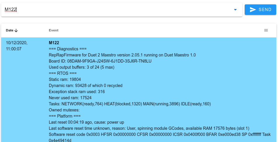
@dc42 Yes M122 report correct voltage! Is there any way to know if drivers initialization over SPI or UART is successfully?
-
@iptronica I only assembly 3 step drivers for X Y and Z...
and left empty E0 and E1Here a picture showing a assembled PCB, and the green wire in middle to put EN line at low level

-
@iptronica said in Custom Duet Maestro Step Drivers Enable Pin allways off:
Is there any way to know if drivers initialization over SPI or UART is successfully?
i think M122 will have some clues, but others are probably more familiar with what it all means.
also look at M111 for available debug options.
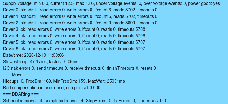
but as you're not getting write or read errors for the three drivers that are installed I'd expect the board to be electrically ok, however it could be the initialization fails because of a missing driver. i'd examine the firmware (i.e source code) or see what dc42 says (or install the missing drivers)
-
I think the stepper driver initialisation is never completing because until very recently, the firmware for the Maestro always expected there to be at least 5 drivers.
-
updating to the very latest 3.2 beta4 sounds like the simplest way to test that
-
That is, just upload 3.2Beta4 and Enable Line in ON now...
So in did MAESTRO Firmware expect to have 5 step drivers, or else it don´t turn it on....
Another way, that should work, can be made by join E0 and E1 uart lines to X.
Thank you for all support....
Now is time for my contribution to project, I've added a simple feature to spindle in CNC mode and will publish it in the CNC forum section.
-
glad you got it sorted!
top tip for next time be more precise with your post; it went from "custom board" to "yes its identical to kicad sources" to "it only has x,y,z drivers" ... the better information you provide the better help you get.
-
@iptronica
I encountered the same problem (the ENABLE line is allways at 3V3)
Can anyone help me