SCARA Arm Configuration Origin
-
Over the last couple of weeks I developed a simple SCARA arm based on a Duet 3 HC Mainboard.
So far I got everything set up based on the instructions on Scara Arms on the duet3d site.
https://duet3d.dozuki.com/Wiki/ConfiguringRepRapFirmwareSCARAPrinterHowever I am struggling with getting the whole thing to run which is probably due to a wrong config (M669).
I get the whole machine homed and at some point I was able to move the head within pretty narrow boundaries. Which is why I kept fiddling with the config and now it doesn't move at all. I always get the error "intermediate position outside machine limits".
Maybe some more information about the arm:
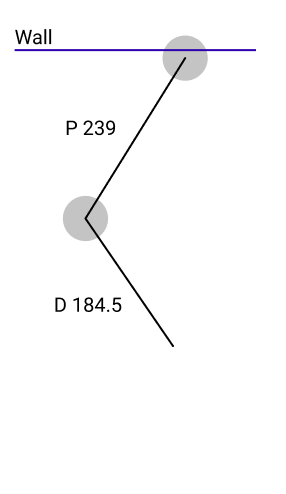
Lengths: Proximal:239mm Distal: 184.5mm
The maximum movement of the proximal joint is about -90 to 90 degrees and the distal joint can move from -90 to 180 since there is no collision between the tool head and the arm which was one important thing I kept in mind while designing it.current setup:
What would the appropriate parameters for my config look like?
Here is my thought process:
X parameter
Arm fully extended:
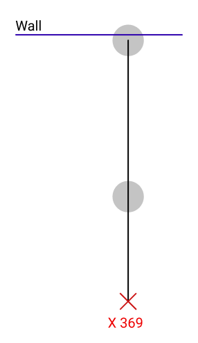
Arm fully collapsed:
guide:
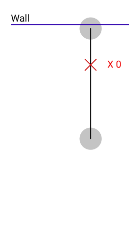
"You should specify xxx and yyy in the M669 command as the location you want for X0, Y0 relative to the proximal joint"which means my offset would be:
"Proximal length" + "Distal length" = X -> 239mm+184.5mm = 423.5mm
"X offset will be positive by an amount somewhat smaller than the square printable X range"
I have no idea how to interpret this, to be honest.Y parameter
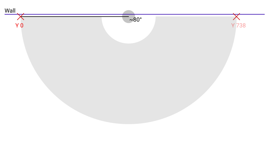
"the Y offset will be negative by about half the square printable Y range."
This would probably be just the arm-length as an offset, right?
Which means
"Proximal length" + "Distal length" = Y -> 239mm+184.5mm = 423.5mmconfig.g:
; Configuration file for Duet 3 (firmware version 3)
; executed by the firmware on start-up
;
; generated by RepRapFirmware Configuration Tool v3.1.10 on Sun Dec 13 2020 17:17:21 GMT+0100 (Mitteleuropäische Normalzeit)

; General preferences
G90                                      ; send absolute coordinates...
M83                                      ; ...but relative extruder moves
M550 P"meta"                           ; set printer name

; Drives
M569 P0.0 S0                             ; physical drive 0.0 goes forwards
M569 P0.1 S0                             ; physical drive 0.1 goes forwards
M569 P0.2 S1                             ; physical drive 0.2 goes forwards
M569 P0.3 S1                             ; physical drive 0.3 goes forwards
M584 X0.0 Y0.1 Z0.2 E0.3                 ; set drive mapping
M350 X16 Y16 Z16 E16 I1                  ; configure microstepping with interpolation

M92 X55.555 Y55.555 Z400.00 E420.00        ; set steps per mm
M566 X900.00 Y900.00 Z60.00 E120.00      ; set maximum instantaneous speed changes (mm/min)
M203 X10000.00 Y10000.00 Z1800.00 E1200.00 ; set maximum speeds (mm/min)
M201 X500.00 Y500.00 Z20.00 E250.00      ; set accelerations (mm/s^2)
M906 X800 Y800 Z1200 E800 I30            ; set motor currents (mA) and motor idle factor in per cent
M84 S30                                  ; Set idle timeout

; Axis Limits
; M208 X-100 Y-100 Z0 S1                         ; set axis minima
; M208 X600 Y600 Z300 S0                   ; set axis maxima

; Endstops
M574 X1 S1 P"!^io0.in"                    ; configure active-high endstop for low end on X via pin ^io0.in
M574 Y1 S1 P"!^io1.in"                    ; configure active-high endstop for low end on Y via pin ^io1.in
M574 Z2 S1 P"^io2.in"                    ; configure active-high endstop for high end on Z via pin ^io2.in

M669 K4 P239 D184.5 A-90:90 B-90:180 X423.5 Y-423.5 ; set SCARA kinematics parameters

; Z-Probe
M558 P0 H5 F120 T6000                    ; disable Z probe but set dive height, probe speed and travel speed
M557 X15:215 Y15:195 S20                 ; define mesh grid

; Heaters

; Fans

; Tools
M563 P0 S"pump" D0 F0                   ; define tool 0
G10 P0 X0 Y0 Z0                         ; set tool 0 axis offsets
G10 P0 R0 S0                            ; set initial tool 0 active and standby temperatures to 0C

; Custom settings are not defined
Here are some photos of the robot. Excuse the messy environment
")
The endstops are hall-effect-sensors at 90° clockwise by the way.


-
@turbomax said in SCARA Arm Configuration Origin:
I get the whole machine homed and at some point I was able to move the head within pretty narrow boundaries. Which is why I kept fiddling with the config and now it doesn't move at all. I always get the error "intermediate position outside machine limits".
To get X0 and Y0 where you have shown, set the M669 X parameter to the distance between the nozzle and the proximal joint when the arm as fully collapsed; and set Y to minus the total arm length when fully extended.
-
Thanks for your quick reply! Entering those values actually fixed the positioning issue. After homing and moving both joints to 0 degrees, the correct coordinates are displayed in the UI.
However, when trying to move the arm in increments via the UI, I still get the same error as before. As far as I understand, pressing the button "X-10" should result in the arm folding in a little and thus the tool head moving 10mm towards the wall. Right?
I still just get the error that it is outside the machine limits...same for every other button I press. Even (and this really confuses me) if I try moving the Z-axis which shouldn't affect the SCARA geometry in any way... -
Still haven't figured it out, but I have another question:
What currently confuses me a little is when coordinates will be treated in which way.
I got the arm to move by adding the
H2parameter, which should ignore all endstops.
But, the values entered for X and Y are interpreted as degrees.Maybe I got something fundamentally wrong, but are there ways to send cartesian coordinates to the board which will then be translated internally to the corresponding joint angles? Or will I always have to do these calculations on my own?
What would the correct format be so the machine interprets the input values as cartesian values? -
Okay another update (but a good one).
At some point I must have commented out theM208lines which probably resulted in the arm thinking that it is outside its limits which blocked every movement.
Putting those lines back in fixed it. Also my question about the coordinates is now fixed. It moves perfectly in the corresponding axes
-
I'm glad you solved it.
For the benefit of anyone else reading this, after homing the arms, you must move the arms to a position that is away from the extremes and within the printing area that you declared using M208. The usual way of doing this is to use a G1 H2 move to move both arms. The example homing files at https://duet3d.dozuki.com/Wiki/ConfiguringRepRapFirmwareSCARAPrinter#Section_Homing_files do this. However, I think a regular G0 move ought to work too.