Duet2 Wifi fan runs constantly
-
Rebuilding my Replicator 2X with some upgrades, one of those is switching to Noctua fans for the hot ends. I have a pair of buck converters attached to fan1 and fan2, leaving fan0 empty. fan1 starts as soon as the board powers up, and won't turn off. Not sure whats going on with it, the fans should be set to thermostatic control and turn on as needed.
Here's my config:
; General preferences M111 S0 ; Debugging off G21 ; Work in millimetres G90 ; Send absolute coordinates... M83 ; ...but relative extruder moves M555 P2 ; Set firmware compatibility to look like Marlin M208 X-7 Y0 Z0 S1 ; Set axis minima M208 X252 Y153 Z155 S0 ; Set axis maxima (reduced by offset above) ; Enable Panel Due Connector M575 P1 S1 B57600 ; Enables connector and sets baud rate ; Endstops M574 X1 S1 P"!xstop" ; X min active high endstop switch M574 Y1 S1 P"!ystop" ; Y min active high endstop switch ;Manual Bed Leveling M558 P9 C"^zprobe.in" H5 F500 T4000 X0 Y0 Z1 ; Set Z probe type/mode 9. H=Dive Height. F=Speed the bed moves G31 P25 X-36 Y0 Z2.885 ; Z probe trigger value, offset in relation to nozzle. And trigger height adjustment M557 X40:190 Y20:145 S20 ; Define mesh grid ;M671 x144:94:191 Y10:160:160 P0.5 ; Manual screw adjustment locations ; Drives M569 P0 S1 ; Drive 0 goes backwards M569 P1 S1 ; Drive 1 goes backwards M569 P2 S0 ; Drive 2 goes forwards M569 P3 S0 ; Drive 3 goes forwards M569 P4 S1 ; Drive 4 goes backwards M350 X16 Y16 Z16 E16 I1 ; Configure microstepping with interpolation M92 X88.573186 Y88.573186 Z400 E96.27520187033366 ; Set steps per mm M566 X900 Y900 Z300 E1200 ; Set maximum instantaneous speed changes (mm/min) M203 X1080000 Y1080000 Z600 E96000 ; Set maximum speeds (mm/min) M201 X1000 Y1000 Z100 E2000 ; Set accelerations (mm/s^2) M906 X800 Y800 Z400 E800 I30 ; Set motor currents (mA) and motor idle factor in per cent M84 S30 ; Set idle timeout M584 X0 Y1 Z2 E3:4 ; Set drive assignments ; Heaters M140 H0 M143 S260 ; Set maximum heater temperature to 260C M308 S0 P"bed_temp" Y"thermistor" T100000 B3974 C0 R4700 ; Set thermistor + ADC parameters for heater 0 M308 S1 P"e0_temp" Y"thermistor" T100000 B4725 C7.060000e-8 R4700 ; Set thermistor + ADC parameters for heater 1 M308 S2 P"e1_temp" Y"thermistor" T100000 B4725 C7.060000e-8 R4700 ; Set thermistor + ADC parameters for heater 2 M950 H0 C"bed_heat" T0 ; heater 0 uses the bed_heat pin, sensor 0 M950 H1 C"e0_heat" T1 ; heater 1 uses the e0_heat pin and sensor 1 M950 H2 C"e1_heat" T2 ; heater 2 uses the e1_heat pin and sensor 2 M307 H0 A103.7 C787.7 D1.0 S1.00 B0 ;M307 H0 A38.5 C41.1 D1.4 V24.4 B0 ; Set PID values for Heatedbed - derived from autotune M307 H1 A250.2 C139.5 D5.4 V24.4 B0 ; Set PID values for Extruder 1 - derived from autotune M307 H2 A387.6 C209.9 D5.9 V24.4 B0 ; Set PID values for Extruder 2 - derived from autotune M307 H3 A-1 C-1 D-1 ; Disable the 4th Heater to free up PWM channel on the Duex board. ; Tools M563 P0 D0 H1 ; Define tool 0 G10 P0 X0 Y0 Z0 ; Set tool 0 axis offsets G10 P0 R0 S0 ; Set initial tool 0 active and standby temperatures to 0C M563 P1 D1 H2 ; Define tool 1 G10 P1 X35 Y-0.8 Z0 ; Set tool 1 axis offsets G10 P1 R0 S0 ; Set initial tool 1 active and standby temperatures to 0C M207 S1.2 F1200 ; Set 1.2mm retract distance for G10 command ; Network M550 P"Rep2X-EnStein" ; Set machine name M552 S1 ; Enable network M586 P0 S1 ; Enable HTTP M586 P1 S1 ; Enable FTP M586 P2 S0 ; Disable Telnet ; Fans M950 F0 C"fan1" Q500 ; Set fan 0 value, PWM signal inversion and frequency. M950 F1 C"fan2" Q500 ; Set fan 1 value, PWM signal inversion and frequency. M106 P0 T40:50 H1 ; Set fan 0. Thermostatic control is turned on M106 P1 T40:50 H2 ; Set fan 1. Thermostatic control is turned on M950 S0 C"exp.heater3" ; Define BLTouch probe M564 H0 ; Allow Movement while axes are NOT homed -
@cdthomas9 said in Duet2 Wifi fan runs constantly:
I have a pair of buck converters attached to fan1 and fan2, leaving fan0 empty. fan1 starts as soon as the board powers up, and won't turn off
can you post a picture of your wiring diagram? the facts that you have more than one suggests that it might not be done right.
-
@cdthomas9 said in Duet2 Wifi fan runs constantly:
M106 P0 T40:50 H1 ; Set fan 0. Thermostatic control is turned on
also this makes no sense. you only want the fan to be on between 40 and 50C ?
and you have not configured a part cooling fan
-
@Veti said in Duet2 Wifi fan runs constantly:
T40:50
I think this would start at 40c and ramp the fan speed up to full at 50c.
-
Yes, following the documentation it says that T:40:50 makes it proportional.
I have one buck converter hooked to fan1, so it takes the incoming 24v and outputs 12v to the Noctua fan for heater 1. I have another on fan2 and that's connected to the fan for heater 2. Since I have 2 fans and want them controlled individually I need 2 buck converters.
-
You can feed the 12v output of the buck converter into the VFAN pin of the voltage selector jumper block. This will give 12v to all of the fan headers and you can just connect your fans normally to the fan connections.
Right now it sounds like you're just powering the fans directly from the buck converter and now switching can take place.
-
The buck converters get their power from the fan pins on the Duet, so when one of the fans gets triggered it powers up the buck converter and the attached fan. connecting the buck converter to the PSU full time then routing the power into the VFAN pin sounds like a plan, I may go with that. The thing that concerns me is that the fan1 connector is getting 24v full time, like it is an always-on fan connection.
-
duet switches the fans on the gnd pin. not the power pin.
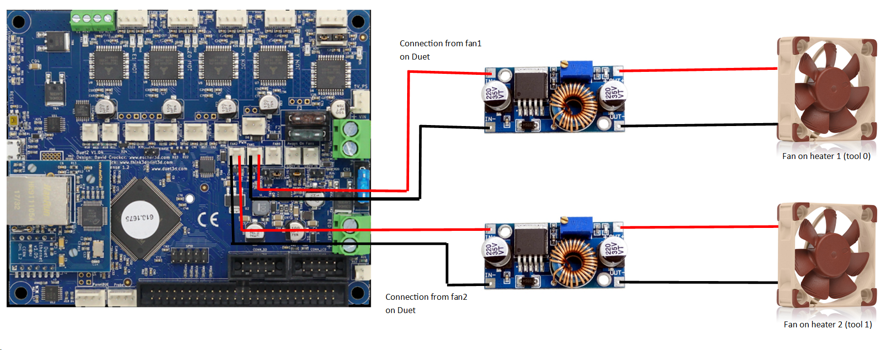
and a buck converter can not handle the pwm frequency switching.for a good picture on wiring. see https://forum.duet3d.com/topic/11147/wiring-diagram-using-12v-fans-on-a-24v-system
-
Right, I remember that now. I'll have to rewire a bit. But, If I have the converter attached to the fan1 and fan2 pins, why is it on now? there should be no connection to ground on fan1 unless the duet is calling for the fan to be on
-
again can you post a picture of your current wiring. this helps us understand your situation
-
-
yes that wont work as the buck converter will not be able to work with the pwm pulsing
-
Ah, gotcha. Thanks, I'll rewire it then.
-
OK, so after rewiring things so that the buck converter is feeding into VFAN, fan1 still runs constantly. I even commented out all of the fan lines in my config.g. Right now I am trying fan0 and fan2, but neither seem to be working. The always on pins and fan1 both get 12v constantly, and fan1 and fan2 don't get anything, even when trying to turn on manually or if I heat up the hot ends.
-
Post a photo of the current wiring and your current config.g
-
; General preferences
M111 S0																	; Debugging off
G21																		; Work in millimetres
G90																		; Send absolute coordinates...
M83																		; ...but relative extruder moves
M555 P2																	; Set firmware compatibility to look like Marlin
M208 X-7 Y0 Z0 S1														; Set axis minima
M208 X252 Y153 Z155 S0													; Set axis maxima (reduced by offset above)

; Enable Panel Due Connector
M575 P1 S1 B57600														; Enables connector and sets baud rate

; Endstops
M574 X1 S1 P"!xstop"													; X min active high endstop switch
M574 Y1 S1 P"!ystop"													; Y min active high endstop switch

;Manual Bed Leveling
M558 P9 C"^zprobe.in" H5 F500 T4000 X0 Y0 Z1							; Set Z probe type/mode 9. H=Dive Height. F=Speed the bed moves
G31 P25 X-36 Y0 Z2.885													; Z probe trigger value, offset in relation to nozzle. And trigger height adjustment
M557 X40:190 Y20:145 S20												; Define mesh grid
;M671 x144:94:191 Y10:160:160 P0.5 										; Manual screw adjustment locations

; Drives
M569 P0 S1																; Drive 0 goes backwards
M569 P1 S1																; Drive 1 goes backwards
M569 P2 S0																; Drive 2 goes forwards
M569 P3 S0																; Drive 3 goes forwards
M569 P4 S1																; Drive 4 goes backwards
M350 X16 Y16 Z16 E16 I1													; Configure microstepping with interpolation
M92 X88.573186 Y88.573186 Z400 E96.27520187033366						; Set steps per mm
M566 X900 Y900 Z300 E1200												; Set maximum instantaneous speed changes (mm/min)
M203 X1080000 Y1080000 Z600 E96000										; Set maximum speeds (mm/min)
M201 X1000 Y1000 Z100 E2000												; Set accelerations (mm/s^2)
M906 X800 Y800 Z400 E800 I30											; Set motor currents (mA) and motor idle factor in per cent
M84 S30 																; Set idle timeout
M584 X0 Y1 Z2 E3:4														; Set drive assignments

; Heaters
M140 H0
M143 S260																; Set maximum heater temperature to 260C
M308 S0 P"bed_temp" Y"thermistor" T100000 B3974 C0 R4700				; Set thermistor + ADC parameters for heater 0
M308 S1 P"e0_temp" Y"thermistor" T100000 B4725 C7.060000e-8 R4700		; Set thermistor + ADC parameters for heater 1
M308 S2 P"e1_temp" Y"thermistor" T100000 B4725 C7.060000e-8 R4700		; Set thermistor + ADC parameters for heater 2
M950 H0 C"bed_heat" T0													; heater 0 uses the bed_heat pin, sensor 0
M950 H1 C"e0_heat" T1													; heater 1 uses the e0_heat pin and sensor 1
M950 H2 C"e1_heat" T2													; heater 2 uses the e1_heat pin and sensor 2
M307 H0 A103.7 C787.7 D1.0 S1.00 B0
;M307 H0 A38.5 C41.1 D1.4 V24.4 B0										; Set PID values for Heatedbed - derived from autotune
M307 H1 A250.2 C139.5 D5.4 V24.4 B0										; Set PID values for Extruder 1 - derived from autotune
M307 H2 A387.6 C209.9 D5.9 V24.4 B0										; Set PID values for Extruder 2 - derived from autotune
M307 H3 A-1 C-1 D-1														; Disable the 4th Heater to free up PWM channel on the Duex board.

; Tools
M563 P0 D0 H1															; Define tool 0
G10 P0 X0 Y0 Z0															; Set tool 0 axis offsets
G10 P0 R0 S0															; Set initial tool 0 active and standby temperatures to 0C
M563 P1 D1 H2															; Define tool 1
G10 P1 X34 Y0 Z0														; Set tool 1 axis offsets
G10 P1 R0 S0															; Set initial tool 1 active and standby temperatures to 0C
M207 S1.2 F1200															; Set 1.2mm retract distance for G10 command

; Network
M550 P"Rep2X-EnStein"													; Set machine name
M552 S1																	; Enable network
M586 P0 S1																; Enable HTTP
M586 P1 S1																; Enable FTP
M586 P2 S0																; Disable Telnet

; Fans
M950 F0 C"fan0" Q500													; Set fan 0 value, PWM signal inversion and frequency.
M950 F1 C"fan2" Q500													; Set fan 1 value, PWM signal inversion and frequency.
M106 P0 T40:50 H1														; Set fan 0. Thermostatic control is turned on
M106 P1 T40:50 H2														; Set fan 1. Thermostatic control is turned on
M950 S0 C"exp.heater3"													; Define BLTouch probe


M564 H0 ; Allow Movement while axes are NOT homed
!
!
-

-
I fear that you may have fried a mosfet or something with the previous wiring setup so that Fan1 is failed in the on position.
Connect a fan to the Fan1 port
SendM950 F1 C"fan1"followed byM106 P1 S1andM106 P1 S0is it able to control the fan?
-
No joy on that, I also tried this for fan2 as well, no control for any fan PWM channel it seems. I haven't had this board long at all either.
-
@cdthomas9 said in Duet2 Wifi fan runs constantly:
No joy on that, I also tried this for fan2 as well, no control for any fan PWM channel it seems. I haven't had this board long at all either.
Well if you had both convertors connected and applied power you may have fried both fan mosfets.
Frederick