Modify SCARA kinematics to add a 3rd rotational wrist joint?
-
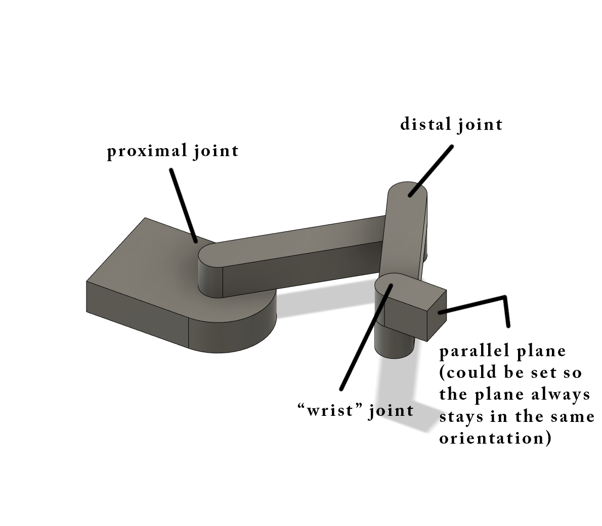
I have been developing and building a 4-axis (I think) SCARA arm/3D printer. It has a linear ball-screw driven Z-axis, and 3 joints (proximal, distal, and wrist).
This is the entire machine minus the wrist joint:

This is the wrist joint:

This wrist joint would add the ability to either have the tool always be pointed in the same direction or allow the wrist angle to be set using a 3rd rotational axis which could either use a U axis or a W axis and would allow for a 45 degree hotend and the ability to use the ZHAW slicer and printing using a 45 degree rotating hotend.
This is a concept of having the tool be able to stay in the same orientation/position:

Currently, the wrist joint uses a NEMA11 motor which is mounted to the joint/distal arm to control the position of the joint.
The problem is that I am terrible at coding and modifying the kinematic systems that are already in place. My current change has it so that the wrist joint will always stay in the same position and modifies the SCARA kinematics class which keeps the joint in the same orientation:
//debugPrintf("psi = %.2f, theta = %.2f\n", psi * RadiansToDegrees, theta * RadiansToDegrees);


	motorPos[X_AXIS] = lrintf(theta * stepsPerMm[X_AXIS]);

	motorPos[Y_AXIS] = lrintf((psi - (crosstalk[0] * theta)) * stepsPerMm[Y_AXIS]);

	motorPos[Z_AXIS] = lrintf((machinePos[Z_AXIS] - (crosstalk[1] * theta) - (crosstalk[2] * psi)) * stepsPerMm[Z_AXIS]);

	motorPos[3] = lrintf(-1 * (theta + psi) * stepsPerMm[3])
This works for now, but it does not allow angular control of the wrist to my knowledge.
My idea would be to add some other definition to the SCARA kinematics class (I was thinking "W" for wrist) which would allow for the rotation of the wrist joint. A gcode signal in the M669 command which would include "W0" meaning that the wrist joint would hold its orientation in relation to the x-axis, and the "W1" command which would allow for a gcode defined rotational position in relation to the x-axis using the U or W command like a G1 X50 Y50 Z50 U/W90 which would have the tool 90degrees clockwise to the x-axis I believe. A "W3" command could even be used so the tool stays static and has no movement, so it is always in line with the distal arm. Any of the "W" commands could be changed to make more sense this is just my idea.
From my terrible understanding of code it would be something like:
motorPos[3] = lrintf(((-1 * (theta + psi)) + U-Angle Position) * stepsPerMm[3])Which would keep the tool in the same orientation and then add or subtract the rotational position value.
I don't know how to implement the configuration of the "W" command using code but that is my best attempt at it. How would I/someone go about trying to configure or even make a new kinematics class for this? Help would be appreciated.