Probe stopped triggering, 4 flashes.
-
So I've had this IR probe for a while. The printer hasn't changed much in months, and it's been working perfectly fine.
My only change to the config is I sometimes have to make small adjustments to the trigger height. I figured that this is because of small changes in the location of the sensor mount, since it's mounted to the fan shroud on an E3D v6 style nozzle, and I believe that vibration or stray plastic touching the sensor moves it a little.
I finished an overnight print, and could see the sensor light flashing, and the DWC was showing modulation on the sensor output as it passed over parts of the print. Today, I went to home the axes, and it crashed into the bed. No reaction from the probe at all. It does not react when I put a white object under it. I power cycled the printer, and after a brief delay, I get 4 flashes.
Documention says to be sure that it's connected to a proper input with a pullup resistor. It's connected to the Duet in exactly the same way it was before. I checked the wiring, unplugged it and plugged it all back in, same result.
So did something kill the pullup resistor? Or is it the IR probe? What's my next step in troubleshooting?
I was going to check that the probe pin is at 3.3V, and check it's resistance to the +3.3V rail on the Duet. Will that damage anything? Is there another way to check the IR sensor?
-
Ugh. Sorry, basic info:
Duet Wifi v 1.4(?) Firmware is 3.3(?) Current as of 5/19/2020
DWC 3.1.1Config.g:
; Configuration file for Duet WiFi (firmware version 3) ; executed by the firmware on start-up ; ; generated by RepRapFirmware Configuration Tool v3.1.4 on Wed Sep 23 2020 15:26:21 GMT-0600 (Mountain Daylight Time) ; General preferences G90 ; send absolute coordinates... M83 ; ...but relative extruder moves M550 P"DMG3D01" ; set printer name ; Network M552 S1 ; enable network M586 P0 S1 ; enable HTTP M586 P1 S0 ; disable FTP M586 P2 S0 ; disable Telnet ; Drives M569 P0 S1 ; physical drive 0 goes forwards M569 P1 S1 ; physical drive 1 goes forwards M569 P2 S1 ; physical drive 2 goes forwards M569 P3 S1 ; physical drive 3 goes forwards M569 P4 S1 ; physical drive 4 goes forwards M584 X0 Y1 Z2:4 E3 ; set drive mapping M350 X16 Y16 Z16 E16 I1 ; configure microstepping with interpolation M92 X400.00 Y400.00 Z400.00 E102.80 ; set steps per mm M566 X750.00 Y750.00 Z24.00 E120.00 ; set maximum instantaneous speed changes (mm/min) M203 X6600.00 Y6600.00 Z180.00 E1200.00 ; set maximum speeds (mm/min) M201 X650.00 Y450.00 Z36.00 E250.00 ; set accelerations (mm/s^2) M906 X1200 Y1200 Z800 E800 I30 ; set motor currents (mA) and motor idle factor in per cent M84 S30 ; Set idle timeout ; Axis Limits M208 X0 Y0 Z0 S1 ; set axis minima M208 X240 Y285 Z200 S0 ; set axis maxima ; Endstops M574 X2 S1 P"xstop" ; configure active-high endstop for high end on X via pin xstop M574 Y2 S1 P"!ystop" ; configure active-high endstop for high end on Y via pin !ystop M574 Z1 S2 ; configure Z-probe endstop for low end on Z ; Z-Probe M558 P1 C"zprobe.in" H5 F600 T9000 A4 S0.15 ; set Z probe type to unmodulated and the dive height + speeds G31 P500 X-17 Y0 Z1.95 ; set Z probe trigger value, offset and trigger height M557 X40:190 Y25:225 S25 ; define mesh grid ; Heaters M308 S0 P"bedtemp" Y"thermistor" T100000 B4138 ; configure sensor 0 as thermistor on pin bedtemp M950 H0 C"bedheat" T0 ; create bed heater output on bedheat and map it to sensor 0 M307 H0 B0 S1.00 ; disable bang-bang mode for the bed heater and set PWM limit M140 H0 ; map heated bed to heater 0 M143 H0 S120 ; set temperature limit for heater 0 to 120C M308 S1 P"e0temp" Y"pt1000" R4700 ; configure sensor 1 as PT1000 on pin e0temp M950 H1 C"e0heat" T1 ; create nozzle heater output on e0heat and map it to sensor 1 M307 H1 B0 S1.00 ; disable bang-bang mode for heater and set PWM limit ; Fans M950 F0 C"fan0" Q500 ; create fan 0 on pin fan0 and set its frequency M106 P0 S0 H-1 ; set fan 0 value. Thermostatic control is turned off M950 F1 C"fan1" Q500 ; create fan 1 on pin fan1 and set its frequency M106 P1 S1 H1 T45 ; set fan 1 value. Thermostatic control is turned on ; Tools M563 P0 D0 H1 F0 ; define tool 0 G10 P0 X0 Y0 Z0 ; set tool 0 axis offsets G10 P0 R0 S0 ; set initial tool 0 active and standby temperatures to 0C ; Custom settings M671 X-70.0:290.0 Y137.5:137.5 S2.5 ; Set the Z motor relative locations DMG 08/30/2018 M572 D0 S0.14 ; Set Pressure Advance ; Miscellaneous M575 P1 S1 B57600 ; enable support for PanelDue M501 ; load config-override.g 111 -
When used with a Duet WiFi/Ethernet, the IR sensor is normally used in analog mode. Use P1 in your M558 command,P500 in your G31 command, and expect 4 flashes at power up. That's exactly what I see in your config.g file; but check that your config-override.g file doesn't set a different G31 P parameter.
If you want to use it in digital mode, then in the M558 command you must use P5 and enable the pullup resistor:
M558 P5 C"^zprobe.in" H5 F600 T9000 A4 S0.15
Then expect 2 flashes at power up.
I suggest you run through the commissioning tests, to see whether in analog mode you get the expected readings of about 0, 465 and 535. It may be that the output wire has become disconnected.
-
Well, I've checked the physical connection, and it seems ok. I only get zero from the output, plus I get no LED indicator when I place a light colour object under the sensor.
So the 4 flashes is normal. I only quickly skimmed the documentation when it failed, so I didn't realize that I was reading for digital mode (Which isn't really what I want anyway.)
config-override.g is a blank file. Also, I changed the M558 command to P0 so that I could get some printing done, and that took, so nothing else is setting the probe type.
Anyway, I'll re-check the output wire, though with no LED reaction I don't think that's the case.
-
@SupraGuy said in Probe stopped triggering, 4 flashes.:
Well, I've checked the physical connection, and it seems ok. I only get zero from the output, plus I get no LED indicator when I place a light colour object under the sensor.
That indicates a failure of the optical system. Are the two IR diodes and the phototransistor still in place? Sometimes they get knocked off if the sensor collides with something.
-
Well, that's the answer. I didn't think that the sensor hit anything during that print. Chances are that the LED is buried somewhere in the infill of the part on the printer, since it's nowhere around the printer as far as I can see. I was printing 5 parts with a total of 74mm height and low infill, so if it fell off during printing, it could have fallen right in and I'd never notice.I'm not very confident with SMD soldering. I do lots of PCBs with through-hole though. I guess I need to get used to it. Through hole components are getting harder to find.
-
If you have a thin tip for your iron it's not too hard. Flux is your friend.
-
Well, I ordered some SMD IR LEDs using the part number from the schematic. I've been looking at SMD soldering techniques. Generally it seems to be the same, but more careful, except if using a heat gun. I'm thinking of getting a heat gun too.
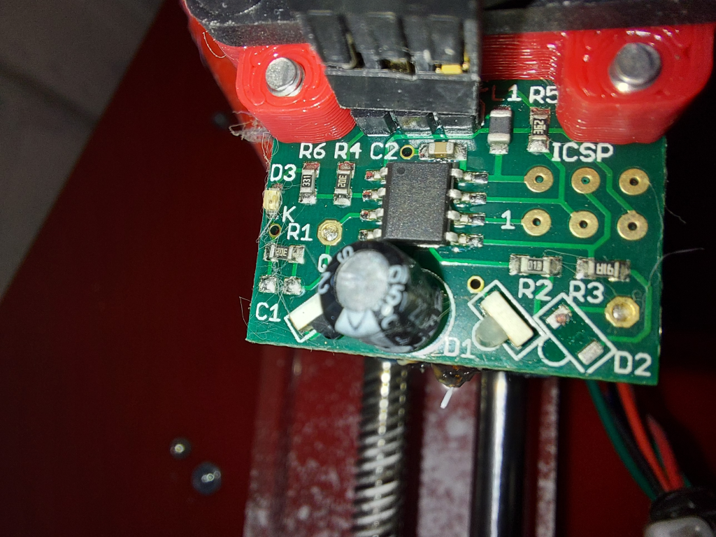
In the meantime, I stole the IR board off of my old printer (Which is actually a newer IR board, as it happens.) Neither one seems to have anything soldered for C1, and the board works perfectly, so I assume that's normal. I guess the solder blobs with the air gap are adequate for the very small value capacitor.
Hopefully I can resurrect this board, because the "local" supplier is out of stock.
Lead screw driven printer, powered by Duet 2 Wifi
MPCNC powered by Duet 2 Wifi
CoreXY printer driven by Duet 3 6HC
LowRider CNC powered by Duet 2 Wifi -
And... In true DIYer fashion, I'll be buying a new heat gun, syringe of solder paste, and another of flux, the SMD IR LED.
So I'm going to fix a $40 board with an $0.87 part.. And $115 in tool and supplies purchases. I've almost talked myself into a somewhat more expensive heat gun, too. Well, we'll have to see how it goes with this one. It's not the cheapest, but it's far from the most expensive one.
My concern is partly getting the LED in place at the correct angle. I'm also a bit concerned that maybe I should replace both in order to ensure that they completely match, but I think wht will happen is that the trigger height will vary some. As long as the nozzle is still above the build surface and it's consistent, I'll be okay with it though.
-
@SupraGuy said in Probe stopped triggering, 4 flashes.:
Neither one seems to have anything soldered for C1, and the board works perfectly, so I assume that's normal.
I confirm, that is normal. I determined that C1 is not needed because the phototransistor has adequate capacitance to suppress high frequency interference.
Replacing just one IR LED will probably work, but if it leads to a trigger height that is too low or too high, replace the other one too. The trigger height range we accept during testing is 2.5 to 3.5mm between the edge of the board and the bed, when using a clean 3mm thick glass bed with black paper underneath.
Duet WiFi hardware designer and firmware engineer
Please do not ask me for Duet support via PM or email, use the forum
http://www.escher3d.com, https://miscsolutions.wordpress.com -

May I present: my first ever successful SMD solder job.I just tested the board, and it triggers properly. I haven't measured trigger distance, but it looks appropriate. Certainly within usable tolerances.
-
Nice work. The sense of accomplishment is well worth the cost of the tools.