RRF3 GPIO Confusion
-
I have been on the path of upgrading my Duet 2 Wifi to version 3.2.2 for some weeks now and have slowly been working through the issues of changes to various of the G Codes.
A few days ago I had the printer (home built AM 8 working perfectly) and then foolishly decided to get my RGB LEDs working. Got all excited when they worked as advertised but then discovered that I got the dreaded "G28 Z Probe already triggered" when I tried to home it.
Despite commenting out the LED comments the G28 fault remains.
I have spent the last two days searching through every reference I can find but there is virtually no information available on aspects of the M950 command. The RRF 3 Overview Dozuki is confusing at best and I I note that others have made the same comment. So once again I am forced to trouble the forum for answers to my latest issue.
My current Config .G is:
; General preferences
G90 ; send absolute coordinates...
M83 ; ...but relative extruder moves
M550 P"Peter Cartesian" ; set printer name; Network
M552 S1 ; enable network
M586 P0 S1 ; enable HTTP
M586 P1 S0 ; disable FTP
M586 P2 S0 ; disable Telnet
M552 S1 ; enable WiFi; Drives
M569 P0 S0 ; physical drive 0 goes backwards
M569 P1 S1 ; physical drive 1 goes forwards
M569 P2 S1 ; physical drive 2 goes forwards
M569 P3 S1 ; physical drive 3 goes forwards
;M569 P4 S1 ; physical drive 4 goes forwards
M584 X0 Y1 Z2 E3 ; set drive mapping
M350 X16 Y16 Z16 E16 I1 ; configure microstepping with interpolation
M92 X100.00 Y100.00 Z400.00 E419.78 ; set steps per mm
M566 X900.00 Y900.00 Z12.00 E120.00 ; set maximum instantaneous speed changes (mm/min)
M203 X6000.00 Y6000.00 Z180.00 E6000.00 ; set maximum speeds (mm/min)
M201 X500.00 Y500.00 Z250.00 E10000.00 ; set accelerations (mm/s^2)
M906 X800 Y800 Z800 E800 I30 ; set motor currents (mA) and motor idle factor in per cent
M84 S30 ; Set idle timeout; Axis Limits
M208 X0 Y0 Z0 S1 ; set axis minima
M208 X215 Y215 Z240 S0 ; set axis maxima; Endstops
M574 X1 S1 P"xstop" ; configure active-low endstop for low end on X via pin !xstop
M574 Y1 S1 P"ystop" ; configure active-low endstop for low end on Y via pin !ystop
M574 Z1 S2 ; configure Z-probe endstop for low end on Z; Z-Probe
M950 S0 C"exp.heater7" ; create servo pin 0 for BLTouch
M558 P9 C"^zprobe.in" H5 F120 T6000 ; set Z probe type to bltouch and the dive height + speeds
G31 P500 X24 Y0 Z1.69 ; set Z probe trigger value, offset and trigger height #####################
M557 X20:215 Y15:180 S20 ; define mesh grid; Heaters
M308 S0 P"bedtemp" Y"thermistor" T100000 B4138 ; configure sensor 0 as thermistor on pin bedtemp
M950 H0 C"bedheat" T0 ; create bed heater output on bedheat and map it to sensor 0
M307 H0 R0.392 C310.5 D7.10 S1.00 V23.9 ; Pid Tune 3 March 2021
M140 H0 ; map heated bed to heater 0
M143 H0 S120 ; set temperature limit for Heated Bed to 120C
M308 S1 P"e0temp" Y"thermistor" T100000 B4138 ; configure sensor 1 as thermistor on pin e0temp
M950 H1 C"e0heat" T1 ; create nozzle heater output on e0heat and map it to sensor 1
M307 H1 R6.299 C94.8 D1.64 S1.00 V24.0 ; Pid Tune 3 March 2021
M143 H1 S280 ; set temperature limit for heater 1 to 280C; Fans
M950 F0 C"Fan0" ; create Blower Fan on pin fan0 and set its frequency
M106 P0 S0 H-1 ; set fan 0 value. Thermostatic control is turned off
M950 F1 C"Fan1" ; set fan 1 value. Thermostatic control is turned on
M106 P1 S255 T45 ; Set Hot end fan to 100% when Temp =45; Tools
M563 P0 S"E3D V7" D0 H1 F0 ; define tool 0
G10 P0 X0 Y0 Z0 ; set tool 0 axis offsets
G10 P0 R0 S0 ; set initial tool 0 active and standby temperatures to 0C; LEDs
;M950 P1 C"exp.heater4" ; Set heater pin 4 for Red led
;M950 P2 C"exp.heater5" ; Set heater pin 5 for Green led
;M950 P3 C"exp.heater6" ; Set heater pin 6 for Blue led;M42 P3 S1.0 ;Set LEDs Blue at start
; Custom settings are not defined
; Miscellaneous
;M575 P1 S1 B57600 ; enable support for PanelDue
T0 ; select first tooland my Homeall is:
M400
G91 ; use relative positioning
G1 H2 Z5 F1200 ; Raise Head 5mmG1 H1 X-220 F1800 ; Move X to Home
G1 H1 Y-220 F1800 ; move Y to homeG90 ; Use Absolute positioning
G1 X125 Y100 F4000 ; Move head to center of bed
G30 ; Lower Head, Stop when probe triggered and set Z to trigger heightG1 X0 Y0 F4000 ; Return Head to Home
-
Can you send M122 and M98 P"config.g" and report the results?
Does the BLTouch pin work correctly?
Double check the white wire for the Bltouch. That is the trigger signal wire.
Otherwise the config and home all look ok.
-
Hi Phaedrux
M122 returns:
M122
=== Diagnostics ===
RepRapFirmware for Duet 2 WiFi/Ethernet version 3.2.2 running on Duet WiFi 1.02 or later
Board ID: 08DGM-917NK-F2MS4-7JKFD-3S46T-1HSNF
Used output buffers: 3 of 24 (10 max)
=== RTOS ===
Static ram: 23460
Dynamic ram: 73392 of which 0 recycled
Never used RAM 15228, free system stack 191 words
Tasks: NETWORK(ready,169) HEAT(blocked,228) MAIN(running,449) IDLE(ready,20)
Owned mutexes: WiFi(NETWORK)
=== Platform ===
Last reset 00:00:39 ago, cause: power up
Last software reset at 2021-03-09 15:31, reason: User, GCodes spinning, available RAM 15192, slot 2
Software reset code 0x0003 HFSR 0x00000000 CFSR 0x00000000 ICSR 0x0041f000 BFAR 0xe000ed38 SP 0x00000000 Task MAIN Freestk 0 n/a
Error status: 0x00
Aux0 errors 0,0,0
MCU temperature: min 15.8, current 20.1, max 20.4
Supply voltage: min 24.0, current 24.1, max 24.2, under voltage events: 0, over voltage events: 0, power good: yes
Driver 0: position 0, standstill, SG min/max not available
Driver 1: position 0, standstill, SG min/max not available
Driver 2: position 0, standstill, SG min/max not available
Driver 3: position 0, standstill, SG min/max not available
Driver 4: position 0, standstill, SG min/max not available
Driver 5: position 0
Driver 6: position 0
Driver 7: position 0
Driver 8: position 0
Driver 9: position 0
Driver 10: position 0
Driver 11: position 0
Date/time: 2021-03-09 16:51:43
Cache data hit count 45937409
Slowest loop: 80.63ms; fastest: 0.21ms
I2C nak errors 0, send timeouts 0, receive timeouts 0, finishTimeouts 0, resets 0
=== Storage ===
Free file entries: 10
SD card 0 detected, interface speed: 20.0MBytes/sec
SD card longest read time 1.0ms, write time 0.0ms, max retries 0
=== Move ===
DMs created 83, maxWait 0ms, bed compensation in use: none, comp offset 0.000
=== MainDDARing ===
Scheduled moves 0, completed moves 0, hiccups 0, stepErrors 0, LaErrors 0, Underruns [0, 0, 0], CDDA state -1
=== AuxDDARing ===
Scheduled moves 0, completed moves 0, hiccups 0, stepErrors 0, LaErrors 0, Underruns [0, 0, 0], CDDA state -1
=== Heat ===
Bed heaters = 0 -1 -1 -1, chamberHeaters = -1 -1 -1 -1
=== GCodes ===
Segments left: 0
Movement lock held by null
HTTP is idle in state(s) 0
Telnet is idle in state(s) 0
File is idle in state(s) 0
USB is idle in state(s) 0
Aux is idle in state(s) 0
Trigger is idle in state(s) 0
Queue is idle in state(s) 0
LCD is idle in state(s) 0
Daemon is idle in state(s) 0
Autopause is idle in state(s) 0
Code queue is empty.
=== Network ===
Slowest loop: 148.36ms; fastest: 0.00ms
Responder states: HTTP(0) HTTP(0) HTTP(0) HTTP(0) FTP(0) Telnet(0), 0 sessions
HTTP sessions: 1 of 8- WiFi -
Network state is active
WiFi module is connected to access point
Failed messages: pending 0, notready 0, noresp 0
WiFi firmware version 1.25
WiFi MAC address 84:f3:eb:83:4c:6f
WiFi Vcc 3.40, reset reason Power up
WiFi flash size 4194304, free heap 26688
WiFi IP address 192.168.87.40
WiFi signal strength -31dBm, mode 802.11n, reconnections 0, sleep mode modem
Clock register 00002002
Socket states: 0 0 0 0 0 0 0 0
M98 P"config.g" returns:
HTTP is enabled on port 80
FTP is disabled
TELNET is disabledThe BLT Pin works correctly and the trigger signal wire has been checked with continuity tester
- WiFi -
-
Is the white wire running alongside heater or motor wires that it could be picking up noise from?
Was the BLtouch working correctly before the LED changes?
What changes did you make? I can't see what would have caused a problem with the BLtouch.Maybe a photo of the install? might give some ideas.
-
Hi Phaedrux
Answers to your questions:- The white wire runs alongside the Hot end fans, thermistor and heater but none of these are active with this current round of testing.
- The BL Touch was working 100% correctly before the LED changes.
- For the LEDs I plugged signal leads for R G & B into Heater pins 4, 5 and 6 on the expansion board. These can be seen in the Photo. The LEDs have their own direct feed from the PSU and are linked through a Darlington Array (ULN2803) chip.
I have also sent the following commands with results as shown:
Power On - BLT cycles and LED goes orange.
M199 - Z Probe at min stop
G92 Z50 DWC shows Z at 50
M119 - Z Probe at min stop
M280 P0 S10 Probe extends blue led illuminates
M119 - z Probe at min stop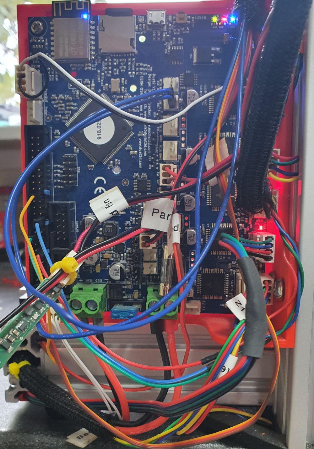
M280 P0 S90 - probe retracts red led illuminates
M119 - z probe at min stop -
Is it just my bad eyes, or is your BLtouch black and white wires connected to the PAneldue port instead of the probe port?
-
DOH!!!!!!!!!!!!!!!!
Often it is the obvious mistake that will only get picked up by another set of eyes.
Thank you Phaedrux it is all working as advertised again.