Duet3 + 1XD -> how do remap DO_EN to OUT1
-
The firmware doesn't provide for remapping the enable output to another pin; and if it did, there would be a short time after power up when the OUT pin was at +24V and the drives enabled, before the configuration was received over CAN and the OUT pin set at 0V.
I suggest you search for "5V to 24V signal converter". The fancy DIN rail mountable ones are stupidly expensive, but there are some cheaper options based on optocouplers, for example http://www.icstation.com/4bit-optocoupler-isolator-level-voltage-converter-board-signal-p-8034.html.
Duet WiFi hardware designer and firmware engineer
Please do not ask me for Duet support via PM or email, use the forum
http://www.escher3d.com, https://miscsolutions.wordpress.com -
@dc42 Thanks for the answer. I am surprised that a company offering ridiculously expensive 1XD extensions, advertising them as suitable for servo control, did not think about it. Of course, I was considering a signal converter, although the one you suggested is much cheaper - thank you again. For now, I will try to use G-codes to turn drives on and off when starting and finishing printing. Perhaps I will also look for a software solution to disconnect drives after critical printing stops, when there is no point in resuming interrupted printing.
-
We designed the 1XD board for the types of driver with 5V single ended or 3.3v differential drivers that some of our users have been using for many years. It's only recently that we have received requests for drivers that can talk to PLCs and related devices. We'll consider providing some 24V signal outputs when we next revise the 1XD board.
Duet WiFi hardware designer and firmware engineer
Please do not ask me for Duet support via PM or email, use the forum
http://www.escher3d.com, https://miscsolutions.wordpress.com -
@dc42 Okay, got it. To my knowledge, most line driver controlled servo drives have SON, EMG, RES etc inputs via open collector. By the way, do you know when these expansion cards will be back in stock?
-
@FLOR said in Duet3 + 1XD -> how do remap DO_EN to OUT1:
@dc42 Okay, got it. To my knowledge, most line driver controlled servo drives have SON, EMG, RES etc inputs via open collector.
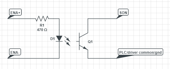
In that case all you need is an opto isolator and input series resistor, driven from the enable outputs of the 1XD.
By the way, do you know when these expansion cards will be back in stock?
There are some either in production now or queued for production, so quite soon. I expect to have more information this evening.
Duet WiFi hardware designer and firmware engineer
Please do not ask me for Duet support via PM or email, use the forum
http://www.escher3d.com, https://miscsolutions.wordpress.com -
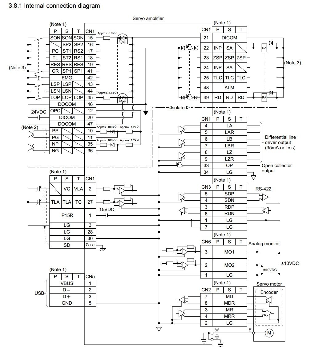
@dc42 I think I messed up something .. I'm not an electronics engineer. Here is the Internal connection diagram of Mitsubishi servos. What exactly should I do to use the EN signal to the SON?
-
Something like this, where D1/Q1 represent the opto isolator.
Duet WiFi hardware designer and firmware engineer
Please do not ask me for Duet support via PM or email, use the forum
http://www.escher3d.com, https://miscsolutions.wordpress.com -
@dc42 Ok, now I'm sure, thank you. You are an exceptionally helpful and patient man.
-
@dc42 And just to be sure - the description for 1XD says: Three digital inputs with permanent 27K pullup resistors, protected against over-voltage: io0.in, io1.in, io2.in.
Am I to understand that I can supply a 24V signal to these inputs directly from the servo drive, or do I also have to use some optocoupler circuit? If so, how to make it harmonize with the previous scheme? -
Yes you can apply 24V directly to those inputs; but be very careful to use the correct pins. However, if there is a difference in ground potential between the servo driver and the Duet (which is likely, if the same PSU supplies the motors as supplies the 24V circuitry in the driver), you should use an opto isolator in order to avoid false readings.