Z-probe released with a solenoid
-
@marcossf said in Z-probe released with a solenoid:
When Z Home or HomeAll never deploy it.
Do your homeall.g and homez.g files now use G30 commands to home the Z axis, instead of G1 H1 Z moves?
Please post your homez.g and homeall.g files as they are now.
-
@dc42 Here are the files.
Homeall.g:
; homeall.g
; called to home all axes
;
; generated by RepRapFirmware Configuration Tool v3.2.3 on Wed Mar 24 2021 10:52:22 GMT+0100 (hora estándar de Europa central)
G91                     ; relative positioning
G1 H2 Z5 F6000          ; lift Z relative to current position
G1 H1 X-205 Y-205 F1800 ; move quickly to X and Y axis endstops and stop there (first pass)
;G1 H2 X5 Y5 F6000       ; go back a few mm
;G1 H1 X-205 Y-205 F360  ; move slowly to X and Y axis endstops once more (second pass)
G1 H1 Z-105 F360        ; move Z down stopping at the endstop
G90                     ; absolute positioning
G92 Z0                  ; set Z position to axis minimum (you may want to adjust this)

; Uncomment the following lines to lift Z after probing
;G91                    ; relative positioning
;G1 Z5 F100             ; lift Z relative to current position
;G90                    ; absolute positioning
Homez.g:
; homez.g ; called to home the Z axis ; ; generated by RepRapFirmware Configuration Tool v3.2.3 on Wed Mar 24 2021 10:52:22 GMT+0100 (hora estándar de Europa central) G91 ; relative positioning G1 H2 Z1 F6000 ; lift Z relative to current position G90 ; absolute positioning G1 X100 Y100 F6000 ; go to first probe point ;M42 P0 S1 ;******just for testing****** ;G4 P400 ;******just for testing****** G30 ; home Z by probing the bed ; Uncomment the following lines to lift Z after probing G91 ; relative positioning G1 Z5 F100 ; lift Z relative to current position G90 ; absolute positioning -
@dc42 this is similar to my probe issues.
there something in the configurator that creates this.
i am using M401/M402 explicitly to couple the probe as part of my macros.
you have to use conditional gcodes to detemine if the probe is attached.i was able to use both G1 H moves as well as G30 with the probe when picked up.
relavant config.g lines
M574 Z1 S2                                       ; configure Z-probe endstop for low end on Z

M558 K0 P8 C"^zprobe.in" H10 R0.5 F240 T9000 A3 S0.03  ; set Z probe type to switch and the dive height + speeds.  Probe A times
and
; ***********************************************************
; deployprobe.g
; ***********************************************************
....
if sensors.probes[0].value[0]!=1000    ; if sensor is value other than 1000 do this
  abort "deployprobe value0 Probe already picked up.  Manually return probe to the dock"

; *****
; gcode for deployment
; *****

if sensors.probes[0].value[0]!=0
   abort "deployprobe endvalue not 0 Probe not picked up!  Print cancelled."
and homez.g is basically-
M401 P0 ; This runs macro file deployprobe G1 X145 Y162.5 F9000 ; go to first probe point M400 G30 -2 M400 G4 P500 M402 P0 -
@sinned6915 Thank you very much. In our case we need to adapt your code and macros a bit because we do not have to take a sled, but when we do a test we do not lose anything.
The only thing the solenoid does is deploy or hide a probe. Once deployed, it activates an optoendstop by touching the probe to the bed. Simple.It is quite clear that it is something in the homing files or in the sw configuration we have, since the activation and the hw part is proven to work.
We came from Marlin and RRF its new for us. Simple things like a homing turn into this "jam"

-
@marcossf i think you need some logic statements in your macros to checks/verify actuation.
my macros work b/c i am checking the conditions of the circuit via probe value.
you could easily add another sensor as an endstop to veify engagment. i dont know if i would use the solenoid trigger as that check, but a seperate sensor. -
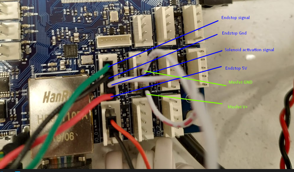
@marcossf, from your photo I can't tell which pins of the 5-pin connector the Z probe opto endstop is wired to. Please provide another photo that shows this clearly, perhaps taken from a different angle.
I think you said that G30 does deploy the probe, but triggering the opto endstop does not stop the G30 movement. Is that right? Does the Z probe reading in the web interface jump to 1000 if you trigger it during G30 movement?
-
@dc42 said in Z-probe released with a solenoid:
@marcossf, from your photo I can't tell which pins of the 5-pin connector the Z probe opto endstop is wired to. Please provide another photo that shows this clearly, perhaps taken from a different angle.

I think you said that G30 does deploy the probe, but triggering the opto endstop does not stop the G30 movement. Is that right?
Yes, it is correct.
Does the Z probe reading in the web interface jump to 1000 if you trigger it during G30 movement?
Yes, it is correct.
-
@marcossf, thanks. I can now see the problem. Your config.g file includes this line:
M584 X40.0 Y0.1 Z121.0 E0.2 ; set drive mappingSo you are driving the Z axis from an expansion board (I presume a Duet 3 Tool Board) at address 121. However, the firmware limitations document at https://duet3d.dozuki.com/Wiki/Duet_3_firmware_configuration_limitations#Section_Temporary_limitations includes this:
Endstop switches and Z probes connected to the main board cannot control motors on an expansion board. This is planned to be fixed in release 3.4.
If you use a Z probe then the Z motors must be connected to the main board. This is planned to be fixed in release 3.4.
So in order to get this working completely, you will need to connect your Z motor to the main board instead.
However, RRF 3.3beta3 released yesterday already includes some of the changes to remove this limitation. If you upgrade to that release, then a G30 command should stop the Z motor even if it is connected to the tool board.
A remaining issue that is not fixed in 3.3beta3 is that when the Z motor stops during probing, there may be a very slight overshoot due to transmission delay over the CAN bus, and there is no correction for this. This overshoot should not matter when doing a single Z probe e.g. for homing Z; however when doing mesh bed probing, the error will build up with each probe attempt. As a result, the accumulated error may cause an apparent tilt in the Y direction.
We have work in progress to undo any overshoot after probing. Meanwhile, it can be reduced by using a low Z probing speed. When homing Z, you may wish to do a fast G30 command at a high probing speed (M558 F parameter) first, then lift Z a few mm and do another G30 at a low probing speed.
HTH David
-
@dc42 said in Z-probe released with a solenoid:
@marcossf, thanks. I can now see the problem. Your config.g file includes this line:
M584 X40.0 Y0.1 Z121.0 E0.2 ; set drive mappingSo you are driving the Z axis from an expansion board (I presume a Duet 3 Tool Board) at address 121. However, the firmware limitations document at https://duet3d.dozuki.com/Wiki/Duet_3_firmware_configuration_limitations#Section_Temporary_limitations includes this:
Endstop switches and Z probes connected to the main board cannot control motors on an expansion board. This is planned to be fixed in release 3.4.
OK, you're right, Z motor are in a external board in this model. In this case a 1LC, but all motors in the final printer are closed loop servos controlled each by a 1XD board.
If you use a Z probe then the Z motors must be connected to the main board. This is planned to be fixed in release 3.4.
So in order to get this working completely, you will need to connect your Z motor to the main board instead.
However, RRF 3.3beta3 released yesterday already includes some of the changes to remove this limitation. If you upgrade to that release, then a G30 command should stop the Z motor even if it is connected to the tool board.
Ok, I can test with the beta3 today and see if this limitation was gone.
A remaining issue that is not fixed in 3.3beta3 is that when the Z motor stops during probing, there may be a very slight overshoot due to transmission delay over the CAN bus, and there is no correction for this. This overshoot should not matter when doing a single Z probe e.g. for homing Z; however when doing mesh bed probing, the error will build up with each probe attempt. As a result, the accumulated error may cause an apparent tilt in the Y direction.
We have work in progress to undo any overshoot after probing. Meanwhile, it can be reduced by using a low Z probing speed. When homing Z, you may wish to do a fast G30 command at a high probing speed (M558 F parameter) first, then lift Z a few mm and do another G30 at a low probing speed.
Still haven't build the mechanical parts for test it. At this moment all boards and pheriperals are laying on the desk, so i can't do measurements or test with the real axes. We need a minimum capable firmware to put in the machine when the build start.
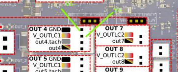
Another thing we tested is remove the external mosfet and use the fan pins to drive the solenoid as you suggest (tested out4 and out7 connectors so far) and we was unable to do with the out4 pin:
We define the pin:
M950 S0 C"out4"   ; create pin 0 for solenoid out4
M106 P0 I-1		; disable the pin as a fan
Tested it with M42 P0 S1 and the pin doesn't out 12v between out4 and gnd. Tested other pins in this bank as well: v_outlc1 its fixed at 12v out and out4.tach its 0v and doesn't switch when its commanded. I don't know how use this pins.
However, with Out7 pins, it is OK.
I can drive the solenoid, M42 P0 S1 enable it giving the 12v out, M42 P0 S0 disable it BUT leaving the pin with 5v instead 0v. This could destroy the solenoid at long term.
How can i get 12v when on and 0v when off??Thanks,
Marcos -
@marcossf said in Z-probe released with a solenoid:
We define the pin:
M950 S0 C"out4" ; create pin 0 for solenoid out4
M106 P0 I-1 ; disable the pin as a fanYou don't need that M106 command, that was for RRF2.
Tested it with M42 P0 S1 and the pin doesn't out 12v between out4 and gnd. Tested other pins in this bank as well: v_outlc1 its fixed at 12v out and out4.tach its 0v and doesn't switch when its commanded. I don't know how use this pins.
Connect the solenoid between voutlc1 (+ve) and out4neg (-ve).
How much current does the solenoid draw, or what is its resistance?
-
@dc42 said in Z-probe released with a solenoid:
@marcossf said in Z-probe released with a solenoid:
We define the pin:
M950 S0 C"out4" ; create pin 0 for solenoid out4
M106 P0 I-1 ; disable the pin as a fanYou don't need that M106 command, that was for RRF2.
OK. The wiki documentation is quite tangled and I find it difficult to see what can and cannot be done in each version.
Tested it with M42 P0 S1 and the pin doesn't out 12v between out4 and gnd. Tested other pins in this bank as well: v_outlc1 its fixed at 12v out and out4.tach its 0v and doesn't switch when its commanded. I don't know how use this pins.
Connect the solenoid between voutlc1 (+ve) and out4neg (-ve).

I measure 12v between these two pins, always. Never switched to 0v.
How much current does the solenoid draw, or what is its resistance?
Solenoid could drive from 3v to 12v DC. The max pulling force its at 12v. Resistance is 44.4Ohm.
-
@marcossf, use the pin labelled out4 (which on the underside of the board is labelled out4_neg), not the OUT 4 GND pin.
-
I can't update the 3.3beta3 from 3.2.2 standalone mode.
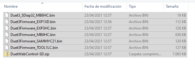
Downloaded the Duet3 files from the https://github.com/Duet3D/RepRapFirmware/releases/tag/3.3beta3
and from DWC > system >upload system files>choose all the files>ok


It keeps "updating" but nothing happens. If I refresh the web its how nothing would hadn't been uploaded.
Retried it three times with same behaviour.
-
@dc42 said in Z-probe released with a solenoid:
@marcossf, use the pin labelled out4 (which on the underside of the board is labelled out4_neg), not the OUT 4 GND pin.
So the solenoid negative pin is out4 pin and positive is V_outlc1 ???
-
@marcossf said in Z-probe released with a solenoid:
So the solenoid negative pin is out4 pin and positive is V_outlc1 ???
Yes. The pin labelled out4 in the MB6HC wiring diagram should be labelled out4_neg. I have asked for the wiring diagram to be corrected.
-
@marcossf said in Z-probe released with a solenoid:
It keeps "updating" but nothing happens. If I refresh the web its how nothing would hadn't been uploaded.
What happens if you send M997?
Do you have a PanelDue in your system? if so, it should display messages during the main board update process.
-
@dc42 Ok, the solenoid working correct in the out4 pin now.
No paneldue attached.
When issued:
M997
Error: M997: In-application programming binary "Duet3_SDiap32_MB6HC.bin" not foundThe files doesn't have been uploaded, but why?
-
@marcossf, try uploading just that file again, then run M997 again.
Which version of Duet web Control is currently running? See the Settings General tab.
-
@dc42 This one:

Unable to upload the files, not even one by one.
I can try some options, try to run from USB (bossa method) or write the files directly to SD card....
-
@marcossf said in Z-probe released with a solenoid:
@dc42 This one:

Unable to upload the files, not even one by one.
I can try some options, try to run from USB (bossa method) or write the files directly to SD card....
You are running a version of DWC older than the version of RRF installed on your main board.
If you send M115, what firmware version does it report? Maybe it has upgraded the main board firmware already.
Are you able to upload the DuetWebControl-SD.zip file from the 3.3beta3 release?