Probe offsets, tool offset, carriage offsets...Madness
-
Hello everybody,
I show you a screenshot seen from below of the printer, for a better interpretation.
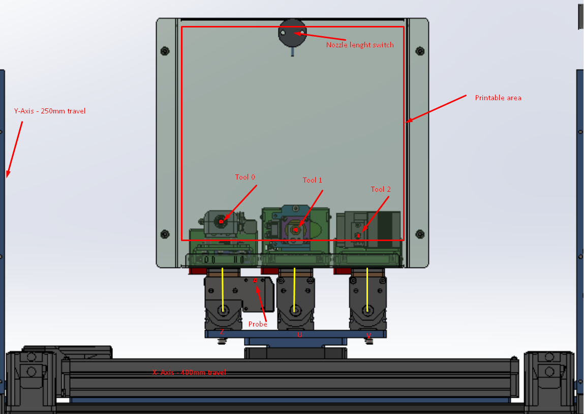
The bed is fixed and the axes move on it in an X and Y gantry with the heads in the X carriage mentioned, where three independent Z U V axes move the tools vertically. The printer has three docks for three different heads that runs along the X axis.
The center of the bed is the coordinate X0, Y0. So the front of the bed is Y-125, back Y125, left X-200 and right X200. The printable area is drawn with the red rectangle.On the Z axis, the first vertical axis, I have a probe for autolevel, and the other two U V axes do not have a probe.
Additionally, I have a fixed endstop in the front center of the bed to set the length of each nozzle, which has a different length (the "nozzles" will be consumables that needs to changed each print job, so automate the Z offset for each tool will be mandatory).
Each printhead tool has 2 switches to set which dock each printhead is in, but for the moment, we will ignore them. At this moment, it is enough to be able to correctly define the offsets of the heads in a specific dock.
Here come the specific questions:
- How do I configure the probe to measure in position X0Y0 of the bed?
If I define G31 X-52 Y-57 Z-5; set Z probe trigger value, offset and trigger height with T0 activated, the probe makes home Z at X0Y0, but if I do T-1 it does it outside of that position X0Y0. Is it necessary to do the G31 with Tn enabled?
- Do I make the offsets of each tool in relation to X0Y0, or relative to the probe, or to the path of X and Y?
- Is it possible to set the offset of each tool with respect to the position of the docks in X (yellow lines)?
How would you configure the offsets on this machine?
This is driving me crazy and I still haven't even been able to get every tool to have the correct offset. Ask me any questions you may have and see if we can make this work.
I leave you my config.g:
; Configuration file for Duet 3 (firmware version 3) ; executed by the firmware on start-up ; ; generated by RepRapFirmware Configuration Tool v3.2.3 on Fri Mar 26 2021 17:48:23 GMT+0100 (hora estándar de Europa central) ; General preferences M552 S1 ; ethernet activation M586 P0 S1 ; enable HTTP M586 P1 S1 ; enable FTP M586 P2 S1 ; enable Telnet G90 ; send absolute coordinates... M83 ; ...but relative extruder moves M550 P"Duet 3" ; set printer name G4 S3 ; wait for expansion boards to start M669 K0 S100 ; cartesian kinematics and segments per second ; Drives M569 P40.0 S1 ; physical drive 40 goes forwards X M569 P41.0 S0 ; physical drive 41 goes forwards Y1 M569 P42.0 S0 ; physical drive 42 goes forwards Y2 M569 P43.0 S0 ; physical drive 43 goes backwards Z1 (Z) M569 P44.0 S0 ; physical drive 44 goes backwards Z2 (U) M569 P45.0 S0 ; physical drive 45 goes backwards Z3 (V) M569 P20.0 S1 ; physical drive 20 goes forwards E0 M569 P21.0 S1 ; physical drive 21 goes forwards E1 M569 P22.0 S1 ; physical drive 22 goes forwards E2 M584 X40.0 Y41.0:42.0 Z43.0 U44.0 V45.0 E20.0:21.0:22.0 ; set axis drive mapping M350 X1 Y1 V1 Z1 U1 V1 E16:16:16 I1 ; configure microstepping with interpolation M92 X150.53 Y150.53 Z100.12 U100.12 V100.12 E409.00:42.0:420.00 ; set steps per mm M566 X900.00 Y900.00 Z500.00 U500.0 V500.0 E120.00:120.00:120.00 ; set maximum instantaneous speed changes (mm/min) M203 X18000.00 Y18000.00 Z12000.00 U12000.00 V12000.00 E1200.00:1200.00:1200.00 ; set maximum speeds (mm/min) M201 X500.00 Y500.00 Z500.00 U500.00 V500.00 E250.00:250.00:250.00 ; set accelerations (mm/s^2) M906 E1000:1000:1000 I30 ; set motor currents (mA) and timeout time M84 S30 ; Disable motor idle current reduction ; Axis Limits M208 X-200:200 Y-125:125 Z0:100 U0:100 V0:100 S1 ; set axis minima and maxima ; Endstops M574 X1 S1 P"!40.io0.in" ; configure active-high endstop for low end on X via pin 40.io0.in M574 Y1 S1 P"!41.io0.in" ; configure active-high endstop for low end on Y via pin 41.io0.in ;M574 Z1 S2 P"!43.io0.in" ; configure active-high endstop for high end on Z via pin 43.io0.in M574 U2 S1 P"!44.io0.in" ; configure active-high endstop for high end on U via pin 44.io0.in M574 V2 S1 P"!45.io0.in" ; configure active-high endstop for high end on V via pin 45.io0.in M574 Z1 S2 ; configure Z-probe endstop for low end on Z ; Z-Probe M950 S0 C"out4" ; create servo pin 0 for solenoid on Out4 M558 P8 C"io3.in" H1 R6.5 F1200 T3000 ; set Z probe type and the dive height + speeds G31 X-52 Y-57 Z-5 ; set Z probe trigger value, offset and trigger height M557 X-100:100 Y-100:100 S20 ; define mesh grid ; Heaters ; Bed heater M308 S0 P"temp1" Y"thermistor" T100000 B4725 C7.06e-8 ; configure sensor 0 as thermistor on pin temp1 for bed thermistor M950 H0 C"out1" T0 ; create bed heater output on out1 and map it to sensor 0 M307 H0 B0 R0.419 C401.2 D2.65 S1.00 ; disable bang-bang mode for the bed heater and set PWM limit M140 H0 ; map heated bed to heater 0 M143 H0 S100 ; set temperature limit for bed heater 0 to 100C ; Syringe preheater M308 S1 P"temp0" Y"thermistor" T100000 B4725 C7.06e-8 ; configure sensor 1 as thermistor on pin temp0 for syringe preheater M950 H1 C"out0" T1 ; create syringe preheater output on out0 and map it to sensor 1 M307 H1 B0 R0.302 C822.1 D3.84 S1.00 V24.0 ; disable bang-bang mode for the syringe preheater and set PWM limit M141 H1 ; map syringe preheater to heater 1 M143 H1 S130 ; set temperature limit for heater 1 to 130C ; FDM heater M308 S2 P"20.temp0" Y"thermistor" T100000 B4725 C7.06e-8 ; configure sensor 2 as thermistor on pin 20.temp0 (FDM) M950 H2 C"20.out0" T2 ; create nozzle heater output on 20.out0 and map it to sensor 2 M307 H2 B0 R2.131 C224.9 D4.61 S1.00 V23.6 ; disable bang-bang mode for heater and set PWM limit M143 H2 S280 ; set temperature limit for heater 2 to 280C ; GEL heater M308 S3 P"21.temp0" Y"thermistor" T100000 B4725 C7.06e-8 ; configure sensor 3 as thermistor on pin 21.temp0 (GEL) M950 H3 C"21.out0" T3 ; create nozzle heater output on 21.out0 and map it to sensor 3 M307 H3 B0 R0.511 C181.9 D6.18 S1.00 V23.8 ; disable bang-bang mode for heater and set PWM limit M143 H3 S140 ; set temperature limit for heater 3 to 130C ; POWDER Heater M308 S4 P"22.temp0" Y"thermistor" T100000 B4725 C7.06e-8 ; configure sensor 4 as thermistor on pin 22.temp0 (POWDER) M950 H4 C"22.out0" T4 ; create nozzle heater output on 22.out0 and map it to sensor 4 M307 H4 B0 R1.622 C246.4 D5.15 S1.00 V23.9 ; disable bang-bang mode for heater and set PWM limit M143 H4 S175 ; set temperature limit for heater 4 to 170C ; Fans ; Tools M563 P0 S"FDM" D0 H2 F0 ; define tool 0 G10 P0 X0 Y0 Z4 ; set tool 0 axis offsets G10 P0 R0 S0 ; set initial tool 0 active and standby temperatures to 0C ; M563 P1 S"GEL" D1 H3 F0 ; define tool 1 G10 P1 X0 Y0 Z4 ; set tool 1 axis offsets G10 P1 R0 S0 ; set initial tool 1 active and standby temperatures to 0C ; M563 P2 S"POWDER" D2 H4 F0 ; define tool 2 G10 P2 X0 Y0 Z5 ; set tool 2 axis offsets G10 P2 R0 S0 ; set initial tool 2 active and standby temperatures to 0C ; External triggers ;M950 J1 C"21.io0.in" ;endstop gel toolhead ;M581 T2 P1 S0 R0 ;endstop gel T2=trigger2-g M591 D1 P1 C"21.io0.in" S1 ;filament monitor for GEL printhead ; Custom settings are not defined -
@marcossf you need to choose a point on the print carriage as the Head Reference Point (HRP). Then define the M208 movement limits in terms of that point, and measure all offsets relative to that.
For that machine I suggest you choose the position of Tool 1 nozzle as the HRP. Alternatively you could define the position of the Z probe as the HRP, which is commonly done on tool changing machines that have a single Z probe attached to the tool pickup.
When probing, the firmware will attempt to position the probe so that the nozzle of the selected tool is at the desired coordinates. If no tool is selected than it positions the HRP at the desired coordinates. For your setup I suggest that you always probe with no tool selected; or alternatively, always probe with tool 0 selected.
Duet WiFi hardware designer and firmware engineer
Please do not ask me for Duet support via PM or email, use the forum
http://www.escher3d.com, https://miscsolutions.wordpress.com -
@dc42 said: Alternatively you could define the position of the Z probe as the HRP, which is commonly done on tool changing machines that have a single Z probe attached to the tool pickup.
It's what we're trying, make our HRP the probe.
The problem is that we make home and probe G31 at the point where the probe efectively touches X0 Y0.
BUT after this, select and applied the offset to the T0 tool, it does not place the nozzle at that coordinate X0 Y0. We are doing something bad.@dc42 said: When probing, the firmware will attempt to position the probe so that the nozzle of the selected tool is at the desired coordinates. If no tool is selected than it positions the HRP at the desired coordinates. For your setup I suggest that you always probe with no tool selected; or alternatively, always probe with tool 0 selected.
We want to probe without any tool loaded, last command in config.g is: T-1, although it ignores it and we have to disable it manually.
In fact, the probe just would be used to topography the surface, because accurate nozzle Z position must be done by the switch in the bed. The Z probe offset should be an aproximation common to all nozzles.
In addition, each toolhead has a different offset, which we have to establish depending on the dock number, the spindle type and the values of this tool (they have different offset, motor parameters, can ID, etc ...).
We intend to do this with the two switches and conditional code, but first of all is achieve that each nozzle prints in its place, before running into added complexities.We will test again, starting from probe point X0 Y0 and no tool selected. One tool at a time.
Back here in a few minutes to give feedback
-
@dc42 Previously we could get the probe avobe the X0Y0 at home, but not anymore.
No matter what offset I put in the config, the printer always move to X0 Y0 (what is half of travel X and half of travel Y) ignoring all G31 probe offsets. The probe always go above the Z probe in X-51 Y-60 related to the phisical X0 Y0 travel axis.
Tool offsets G10 are all zero, and tested homing with T-1.
Is it possible the probe offset can be cached or retained somewhere? Could it not be rewriting itself?
If I can't set the HRP point for the probe badly I will be able to position the offset of the toolheads.
At this point, I don't know what is wrong or I have seriously misconceptions.
-
@marcossf said in Probe offsets, tool offset, carriage offsets...Madness:
Previously we could get the probe avobe the X0Y0 at home, but not anymore.
No matter what offset I put in the config, the printer always move to X0 Y0When does it go to x0y0? What are you sending? Please share your gcode.
-
Sorry, I suppose you have actually shared all of your gcode files here as well: https://forum.duet3d.com/topic/24071/help-with-configuration
-
@phaedrux Yes, its the main thread but i opt for made one specific for each problem.
I'm just sending Homeall or G28.
When I do that home, the probe is placed in the x y position regardless of the offset data that I put.
It is assumed that it would have to be located once the coordinates for the probe are set at the X0 Y0 marked on the bed, with no tool selected.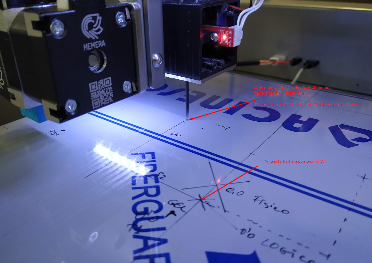
When putting an offset to the T0 tool and selecting it, if the XY position for that tool changes, so the offset of the tool is taken into account, but not the offset of the probe itself that I want to be my HRP fixed point of reference for the tools as @dc42 said.
; Axis Limits
M208 X-200:200 Y-125:125 Z0:100 U0:100 V0:100 S1              	; set axis minima and maxima
; Z-Probe M950 S0 C"out4" ; create servo pin 0 for solenoid on Out4 M558 P8 C"io3.in" H1 R6.5 F1200 T3000 ; set Z probe type and the dive height + speeds G31 X-50 Y-56 Z-5 ; set Z probe trigger value, offset and trigger height M557 X-100:100 Y-125:125 S20 ; define mesh grid X 200mm and Y 250mm from bed center 0.0; Tools M563 P0 S"FDM" D0 H2 F0 ; define tool 0 G10 P0 X0 Y-53.91 Z4 ; set tool 0 axis offsets G10 P0 R0 S0 ; set initial tool 0 active and standby temperatures to 0CHomeall.g:
; homeall.g ; called to home all axes ; ; generated by RepRapFirmware Configuration Tool v3.2.3 on Wed Mar 24 2021 10:52:22 GMT+0100 (hora estándar de Europa central) T-1 G91 ; relative positioning G1 H1 Z100 U100 V100 F2000 ; lift UV relative to current position ;G1 H2 Z100 F2000 G1 H1 X-405 Y-255 F2000 ; move quickly to X and Y axis endstops and stop there (first pass) G90 ; absolute positioning G1 X0 Y0 F2000 G91 ; relative positioning G30 ; probe G90 ; absolute positioning ; Uncomment the following lines to lift Z after probing G91 ; relative positioning G1 Z100 F2000 ; lift Z relative to current position G90 ; absolute positioning -
Any hint, or things to check? @dc42 @Phaedrux
Is the probe offset taken into account when doing an X0 Y0 when homing all?
That is, if I want the probe to place in the center of the X that I have marked (X-50 Y60), why I have to tell it that coordinate in the home process instead X0 Y0?
So what's the point of HRP? Wouldn't it be a known point where the probe thinks it is X0 Y0 and from which, in a relative way, the tool offsets, the autolevel and the center of the real printing area are set?
-
We have solved the problem of HRP and tool offsets.
The problem was that we made relative and absolute incompatible movements in the homing.
We solve it by moving the probe to the X Y coordinate where the X0 Y0 should be in the homing process and after this, make G92 X0 Y0 where G31 is the probe X0 Y0.
From there, we were able to establish that point as HRP and to be able to establish the offset of the toolheads.
It was silly
